
A detailed look at the ProSim737 Combined Config dialog, what it does, and how it works.
Contents
- 1 Introduction
- 2 About the Combined Config
- 3 Accessing the Combined Config
- 4 Combined Config Organization
- 4.0.1 Major System (Top-Level or Main category)
- 4.0.2 Hardware Group (subcategory)
- 4.0.3 Configurable Items (or Item Name)
- 4.0.4 Auto-Configure (Switches and Analog only)
- 4.0.5 Find Indicator (Indicators only)
- 4.0.6 Add Additional (Indicators, Gates, Numerical, Analog only)
- 4.0.7 Hardware Selector Drop-down
- 4.0.8 Search Bar
- 5 Combined Config Hardware Groups
Introduction
Despite being a very complex avionics simulation software, ProSim737 is an easy-to-use and powerful avionics software that faithfully and accurately recreates the complex systems on the Boeing 737. However, the sheer number of growing configurable options and the rapid development of new features created by a small team of developers means new (and existing) functionality isn’t often well documented or immediately clear.
Within the ProSimB738 application is the “Combined config” menu. It allows you to assign physical hardware to functions within ProSim. This powerful feature is how you set up your hardware to work with ProSim, and it’s what makes ProSim so quick and easy to configure.
I hope to help bridge the information gap by providing a quick reference guide to the ProSim737 Combined config and explaining all the assignable values, how they are configured, and any additional helpful information regarding each item. The intent is to take all that scattered knowledge and put it in one easily searchable place.
About the Combined Config
The ProSimB738 System Combined config is the central place within ProSim to assign your physical hardware to the various switch, indicator and other functions within the simulator software. In other words, it’s the main way you interface with the sim. It’s very powerful and easy to use, but there’s a LOT of functions.
Accessing the Combined Config
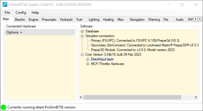
To get to the Combined Config dialog, open the ProSimB738 System module by double clicking the ProSimB738.exe file in its ProSim folder on your computer’s hard drive, or clicking the ProSimB738 shortcut on your desktop, if available.
This will open the ProSimB738 System module.
Click Config in the main menu bar at the top and select Configuration from the drop-down menu. This will open the Configuration dialog.
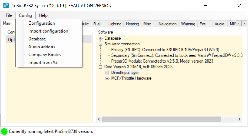
A new configuration window will open.
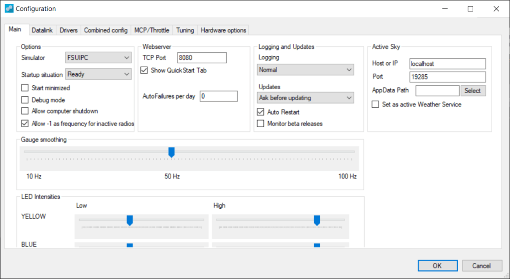
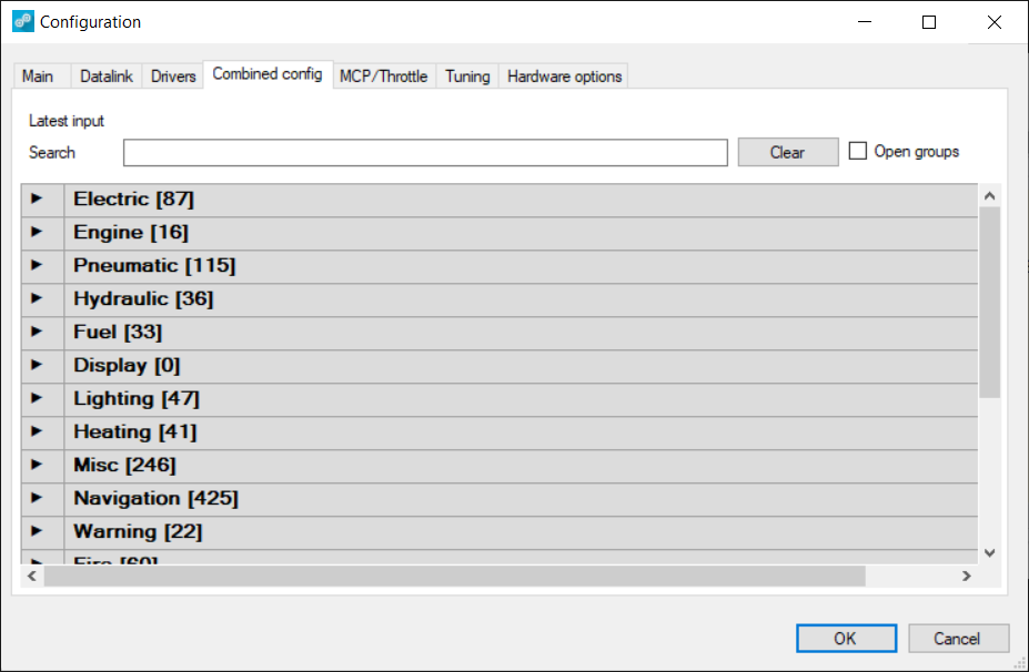
Now click the Combined config Tab from the tabs at the top.
Combined Config Organization
Major System (Top-Level or Main category)
When you first open the Combined config dialog, you will see a collapsed view of all the top-level major system sections. Click the arrow next to the section title to expand and view the associated Hardware Groups.
Hardware Group (subcategory)
Expanding a top-level category reveals the hardware groups available to configure for that system. Click the arrow next to the hardware group title (e.g. SWITCH) to view the configurable items within that group.
Configurable Items (or Item Name)
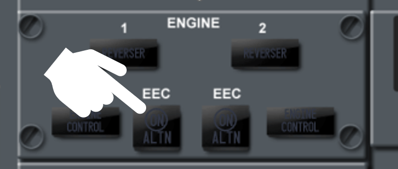
Within the hardware groups you will see the available configurable items listed alphabetically by name. These names are usually self-explanatory, and will normally map to the exact name and state of the hardware item in the cockpit. For example, if the physical button for the left EEC is pushed, then you’ll see the latest input show the interface and port that triggered. You can then map that to the “EEC left Pushed” config item:
Note: If a configurable item has more than one assignable state, you’ll see all the available states listed. Each state can be assigned to a physical hardware position, if needed, though usually it’s not necessary to assign every single state. The OFF state, for example, doesn’t usually need to be assigned to anything but it can be, if you so choose.
The Combined config dialog window is categorized into major aircraft systems, then hardware groups, then configurable items.
 Auto-Configure (Switches and Analog only)
The auto-configure icon makes it quick and painless to assign physical hardware to ProSim inputs. When a toggle switch, rotary switch, potentiometer, or lever/axis are moved, the “Latest input” line at the top of the Combined config dialog will populate, indicating ProSim has found the interface/port the hardware (or hardware position/state) is connected to. You can then click the auto-configure button to automatically assign the detected hardware to that configurable item.
Alternately, you can manually select the interface and port from the list of detected interfaces in the drop-down menu. Unless you’ve documented every input to the interface/port it is connected to, this may be a very tedious task!
 Find Indicator (Indicators only)
The find icon makes it easy to find connected indicators. Clicking the button illuminates every connected indicator in the cockpit and by process of elimination, is able to help you find the exact interface/port the indicator is connected to and assign it to the ProSim configurable item.
 Add Additional (Indicators, Gates, Numerical, Analog only)
The plus button allows you to add more than one hardware item to the ProSim output. With indicators, for example, you could configure one indicator, then click the plus button to add a second indicator that illuminates with the first. With gates, you could have a gate function activate two servo motors at the same time.
Hardware Selector Drop-down
You can use this dropdown to manually configure hardware. The drop-down will show all compatible interfaces that ProSim has identified. When you choose a hardware interface from the drop-down, you will also need to choose the associated port on the interface the hardware is connected to.
Search Bar
To quickly find configurable items without having to know which section/group they fall in, you can type the full or partial name of the item in the search box and the main sections will indicate how manu matching items were found within the section via the section count brackets []. Simply expand the appropriate section to drill down to the item you need to configure.
Or click the “Open groups” check box to automatically expand all sections containing matching items. NOTE: this can be intensive on the PC and may hang ProSim.

Combined Config Hardware Groups
In the Combined config dialog window each main system section contains various groups of hardware. These may include some or all of the following:
| Hardware Group | Description | Examples |
|---|---|---|
| Switch | A physical hardware toggle switch. | On/off switches, momentary push buttons, rotary switches, etc. Basically anything that opens or closes a circuit when in a specific position. |
| Indicator | A lamp or LED, single or dual brightness, used to “indicate” the status of something. They are either on or off. | Indicators are used heavily throughout the cockpit, especially in the FWD overhead. They help call attention to items that need attention. They are primarily Red (critical), Amber (warning), Green (ok) and Blue/White (informational). |
| Gauge | A hardware item that is used to display/indicate positional values via a physical gauge, usually servo-driven. Gauges can be calibrated to ensure its readings are accurate throughout the range of motion. Gauges are calibrated within ProSim by defining gauge positions based on set values. | There are a number of physical gauges in the cockpit including the dual-needle Duct Pressure gauge below. These are typically driven by small servo motors or stepper motors. |
| Gate | Gates are actions that are triggered by events that happen in the sim environment. They are binary states (i.e. ON-OFF). | Gates can be used to play a sound when a certain speed is reached (e.g. V-speed gates). They can also be used to control devices when a switch is pressed (e.g. trim motor activates when trim switch is pressed). Another example is the Thrust Reverser synclock gate which is active only when radar altitude is less than 10 feet or the Air Ground sensor is in ground mode. The gate can be associated with a solenoid on/off action to “lock out” the reversers unless the appropriate conditions are met. |
| Numerical | This outputs a numerical value to your hardware. | Normally used for things like 7-segment displays such as the radio frequency display windows. |
| Analog | This is typically a potentiometer or “pot” (a variable resistor) that is used to adjust the amount of analog signal (e.g. DC voltage) going to something. | Used for brightness knobs in the form of a rotary pot, or connected to a linkage such as a Throttle Handle by using a “slide” or “string” pot. |
| Encoder | This is essentially a smart rotary (digital) that is able to read and report the precise angular position of the shaft. | Typically used for MCP knobs and FLT or ALT pressure knobs, Radio tuning knobs, etc. May also have detents so you can feel each “click” of the rotation. |
| Lever | This is a hardware item with a set range of motion. Lever movement is measured by its connected analog potentiometer or encoder. | Examples would be throttle levers, flap levers, and speedbrake levers that have specific minimum, maximum and pre-set positions in-between (e.g. flap detents, spoiler handle, etc) |
| LCD | Used to output alpha-numeric strings to a dot-matrix style LCD display. | Used by some Plug and Play hardware like Pim’s IRS panel or the Matrix Orbital LCD. LCDs are used for the IRS panel, Elec Panel, and HUD panel (which requires an extra license). |


Hi, if you mean the two rails that run from front to rear and the cross strut, yes those came…