
Linked Control Columns & Loading – Part 2 – The Pitch Axis
Last Updated on April 4, 2026 It has been a long while since I wrote Part 1. Hard to believe. It took time to get things finished up and generally working, and then the rest of the sim had to be built back up on top of it. Throw a bit …

Cockpit Panel Lighting
Real world cockpit panel lighting is dependent on the active power bus. I explain how I set up my panel lighting to function in a similar way, resulting in a more realistic cockpit lighting environment …

Still kicking. Lots of new updates coming soon!
Last Updated on August 27, 2025 It has been a long while since the last post but that doesn’t mean things have been quiet. A lot has been happening behind the scenes over the last year and there are certainly a lot of new things to write about. It just takes …
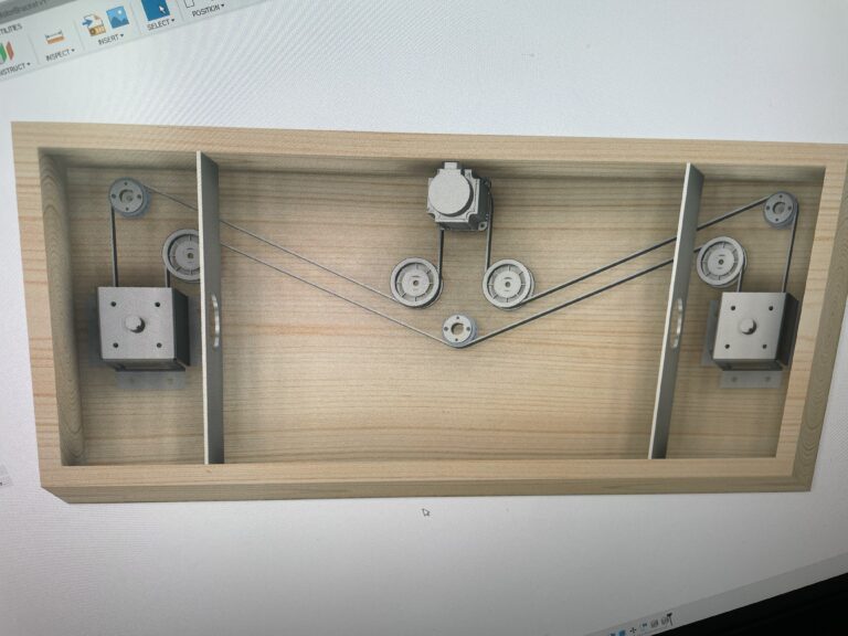
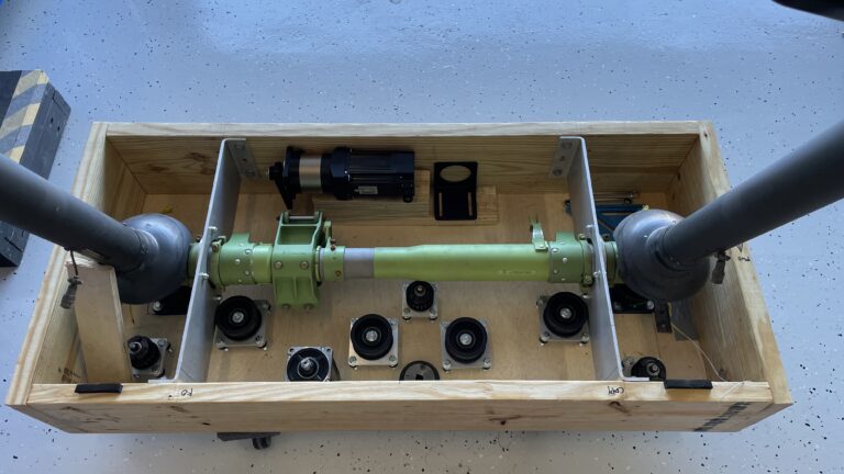
Linked Control Columns & Loading – Part 1 – May the Force be with you!
Last Updated on April 4, 2026 “Try not. Do or do not. There is no try.” —Yoda, Star Wars Episode V: The Empire Strikes Back IntroductionBackgroundFirst, The Real Control ColumnsMy GoalsThe Starting PointChallenges Building my Control ColumnsAlternatives to DIY Control ColumnsStarting my DIY Control Column DesignConcept DrawingsProgress PhotosTo be Continued… Introduction …
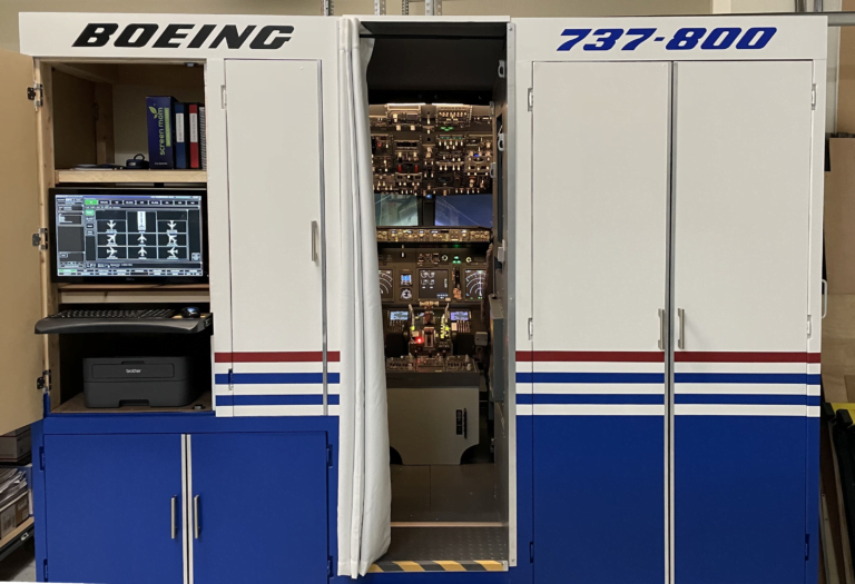
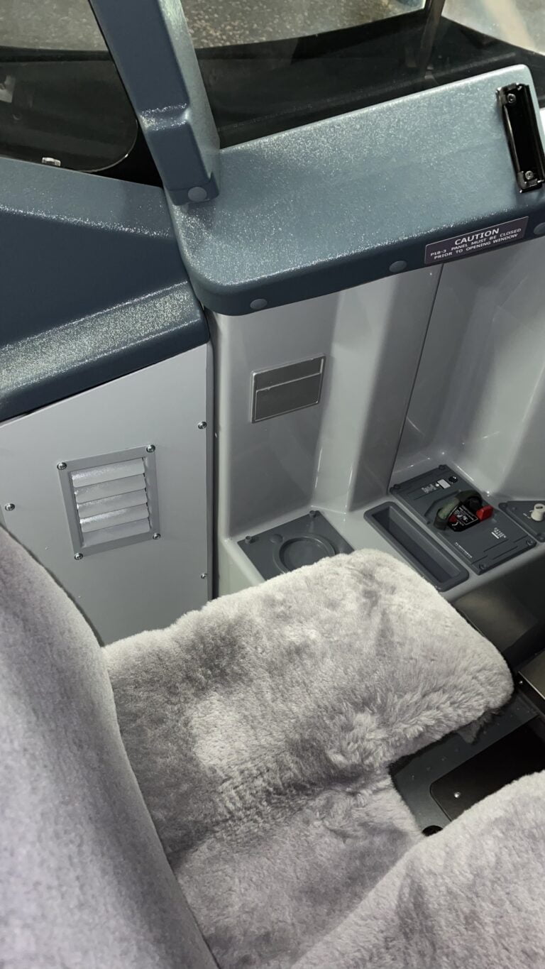
Boeing 737 Sim Update – May 2023 – Bulkhead Paint and Detail
Last Updated on June 1, 2023 It has been a while since my last update. While it may seem things have been pretty quiet, I’ve made quite a bit of progress over the months since then and thought I’d share. Bulkhead Progress The rear bulkhead has been a pretty big project …
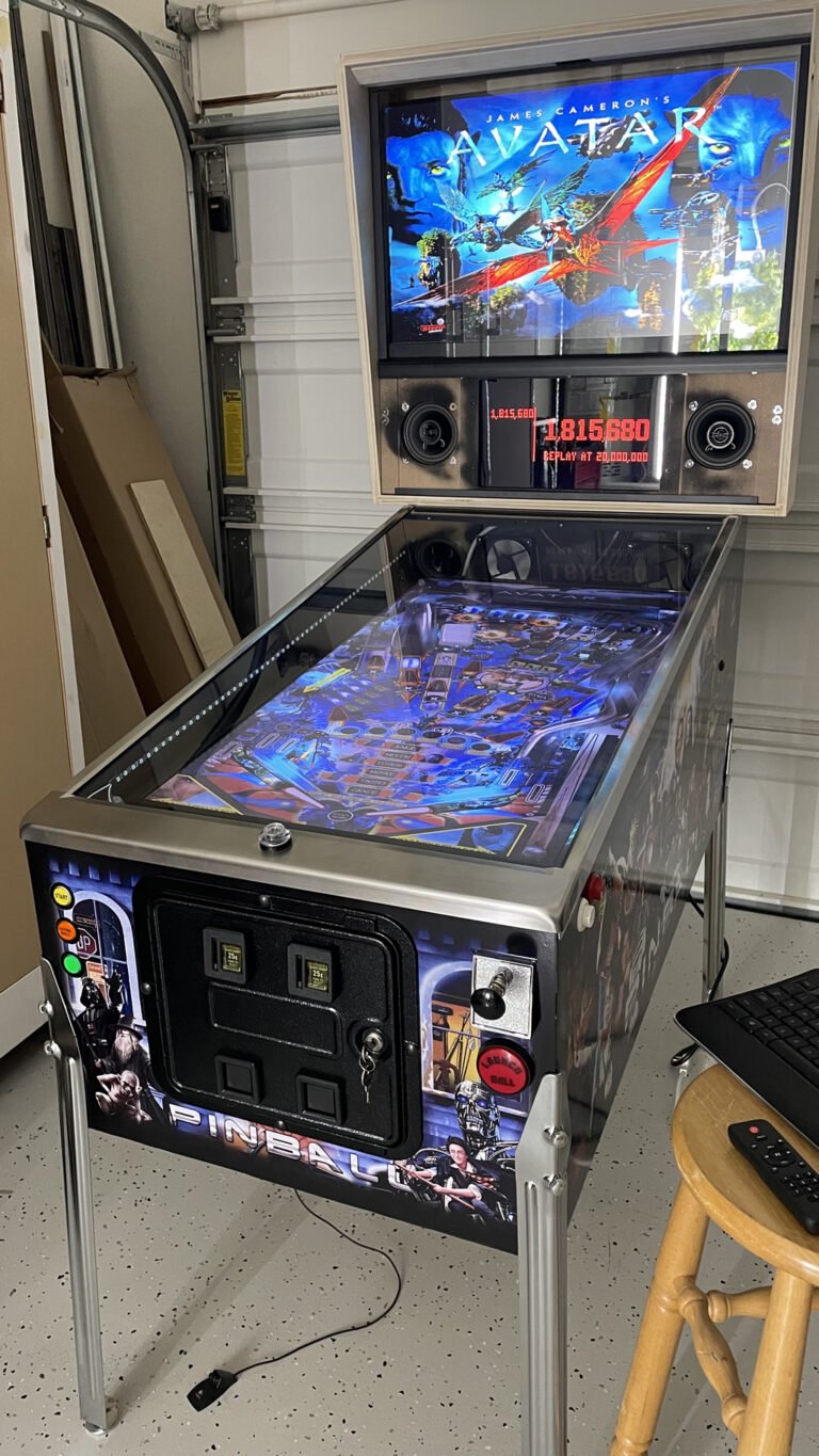
A Different Kind of Simulator – Virtual Pinball!
Sometimes you need a fun diversion from flight simming. So I decided to make my own virtual pinball machine …
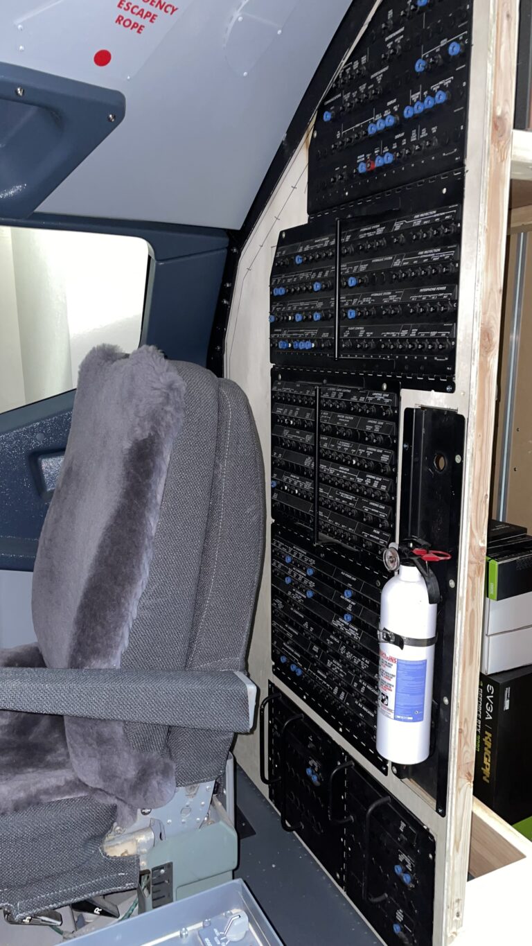
Boeing 737 Sim Update – July 2022 – Circuit Breaker Panels
Working on adding real circuit breaker panels to my 737 cockpit …
Buying Parts for your Home Flight Simulator Cockpit
What do you need to know when buying parts for your home flight simulator cockpit build? …
Building a Boeing 737 Home Cockpit Rear Bulkhead
Time to start enclosing my cockpit shell with a rear bulkhead …
The Devil in the Details – Bringing my Simulated Boeing 737 Cockpit to Life With Some Extra Detail…
Last Updated on December 12, 2023 Adding little details to your home-based flight simulator cockpit can really enhance the realism and enjoyment of the experience. These last weeks I’ve been keeping busy by adding some little cockpit details to add some realism, and tying up some of those nagging loose ends …


Hi, if you mean the two rails that run from front to rear and the cross strut, yes those came…