
Last Updated on April 4, 2026
“Try not. Do or do not. There is no try.”
—Yoda, Star Wars Episode V: The Empire Strikes Back
Introduction
One of the things I’ve wanted for a long time is linked control columns, and it’s the last major item needed to complete my reasonable recreation of a Boeing 737-800 cockpit.
In Part 1 of this blog, I’ll talk about the development of my linked control column design. In a later blog(s), I’ll continue the discussion with further detail about what parts I used and how I made it all work.
Background
When I originally built my sim, I couldn’t afford a linked column setup so I purchased a single used standalone realistic-looking ACE control column which I still use today. Later I added a second standalone ACE column but they obviously still weren’t linked. The second column was added more for a sense of completion and effect than for flying use since generally I fly alone so a linked setup wasn’t critical.
Recently, however, I had a visitor who wanted to fly from the F/O seat. My ACE yoke on that side of the cockpit wasn’t functioning, and that got me thinking maybe it was time to start working toward installing linked columns.
In this article, I’ll be talking about my progress building my own linked control column set up. There’s so much information to try and pack here that it’s near impossible to keep short, so my apologies for the length. Remember, this is only one of probably a million different ways to do this and my solution certainly isn’t perfect, but hopefully you’ll find it inspiring or at least interesting.
First, The Real Control Columns
In the real aircraft, both control columns and control wheels move in unison and, when on auto-pilot, they move automatically to visually indicate what the aircraft automatics are trying to do. The flight controls also have a feel and centering mechanism (think of it as force feedback known as control loading), which effectively adjusts the forces on the controls based on the current flight environment.
Rather than try to explain how it all works when I’m by no means an expert, check out Chris Brady’s awesome 737 technical channel on YouTube where he goes quite in-depth on how the 737 flight controls work:
- Boeing 737 Flight Controls – Pitch (Time 46:11 for feel information)
- Boeing 737 Flight Controls – Roll and Speedbrakes
- Boeing 737 Flight Controls – Yaw
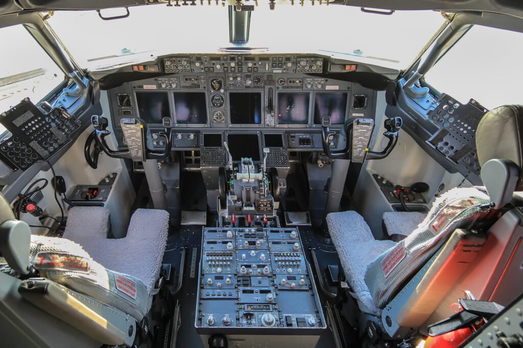
A Real 737NG Cockpit
My Goals
As you prob ably ascertained by now, my goal is to try and replicate the real aircraft linked columns as best I can within the limited knowledge, skills, and funds I have. Ideally I’d like to have the following:
- Both columns move together forward and aft, and the control wheels move together when rolled left and right (i.e. linked) (required)
- I want the controls to move automatically to follow the auto-pilot, and adjust based on trim settings (very important)
- I want to add some “feel” to the controls so that depending on the flight situation, the controls become easier or more difficult to move (less important but a nice to have)
A complete solution like this would probably set you back $20-30K USD. You’re talking not only the hardware, but the software and engineering to make it all work and trust me, after building my own solution, I understand why it can cost so much.
Obviously, though, that price point is not going to work for me so I’m going to try and figure out how to do it myself for cheaper.
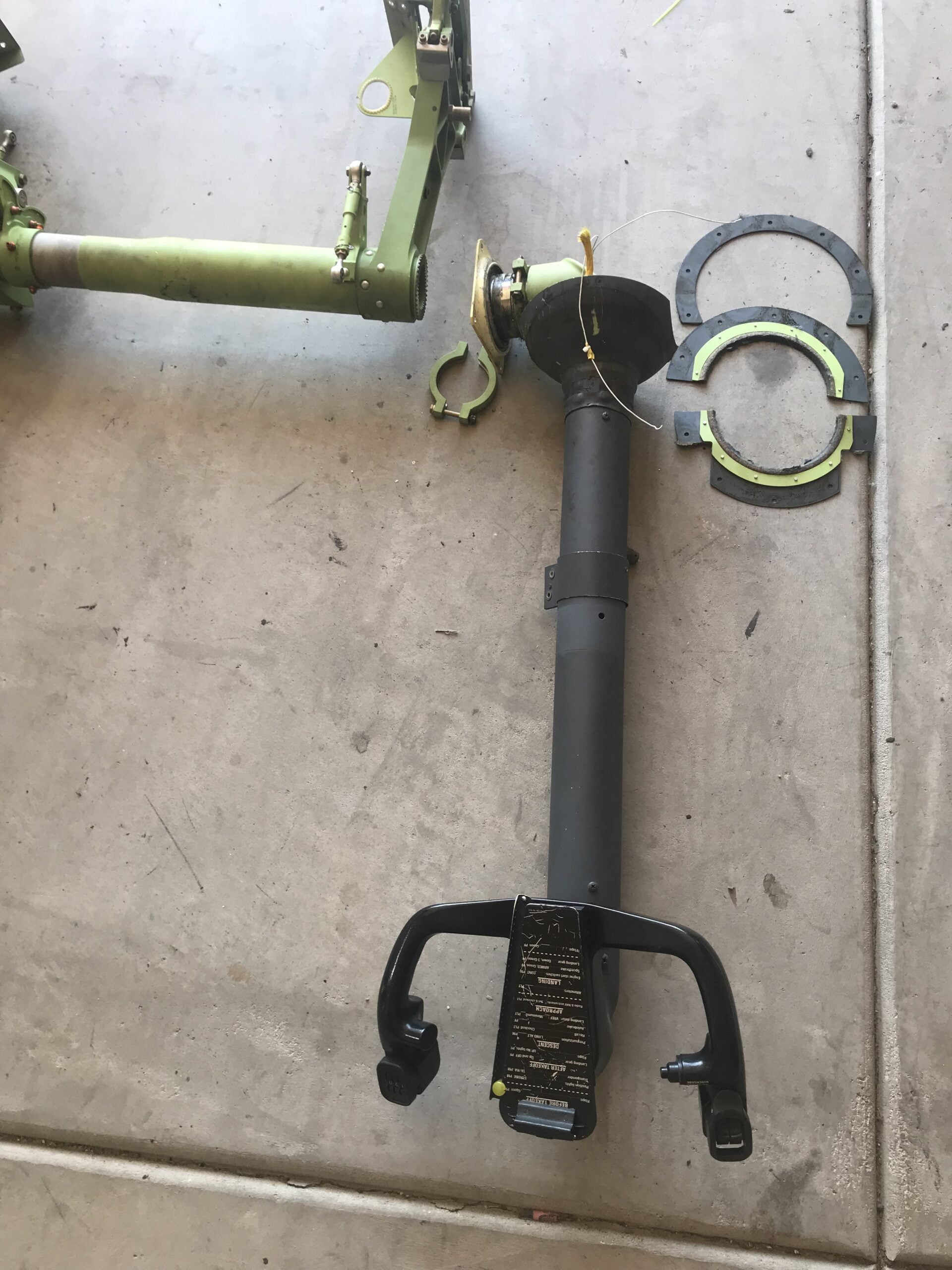
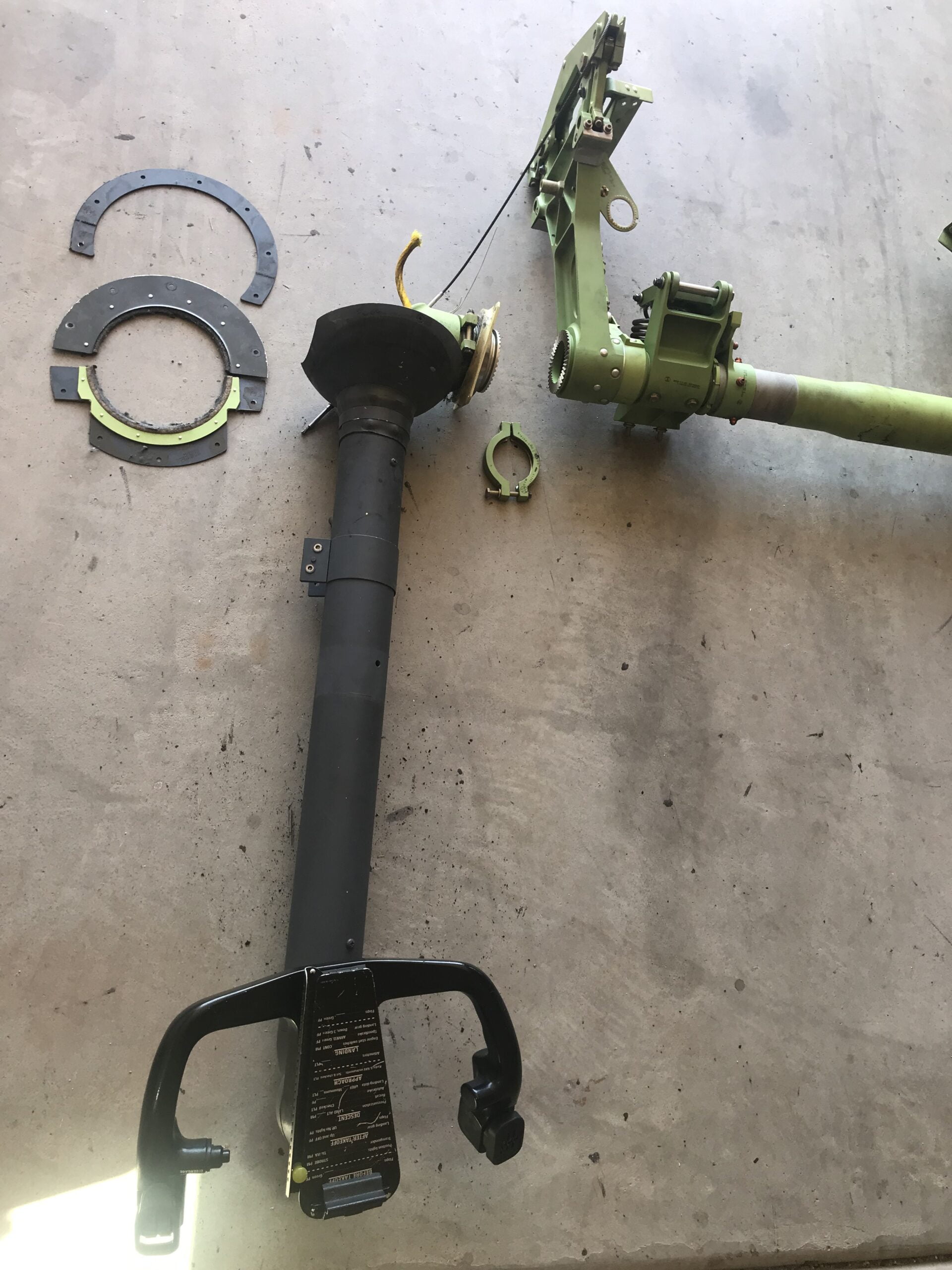
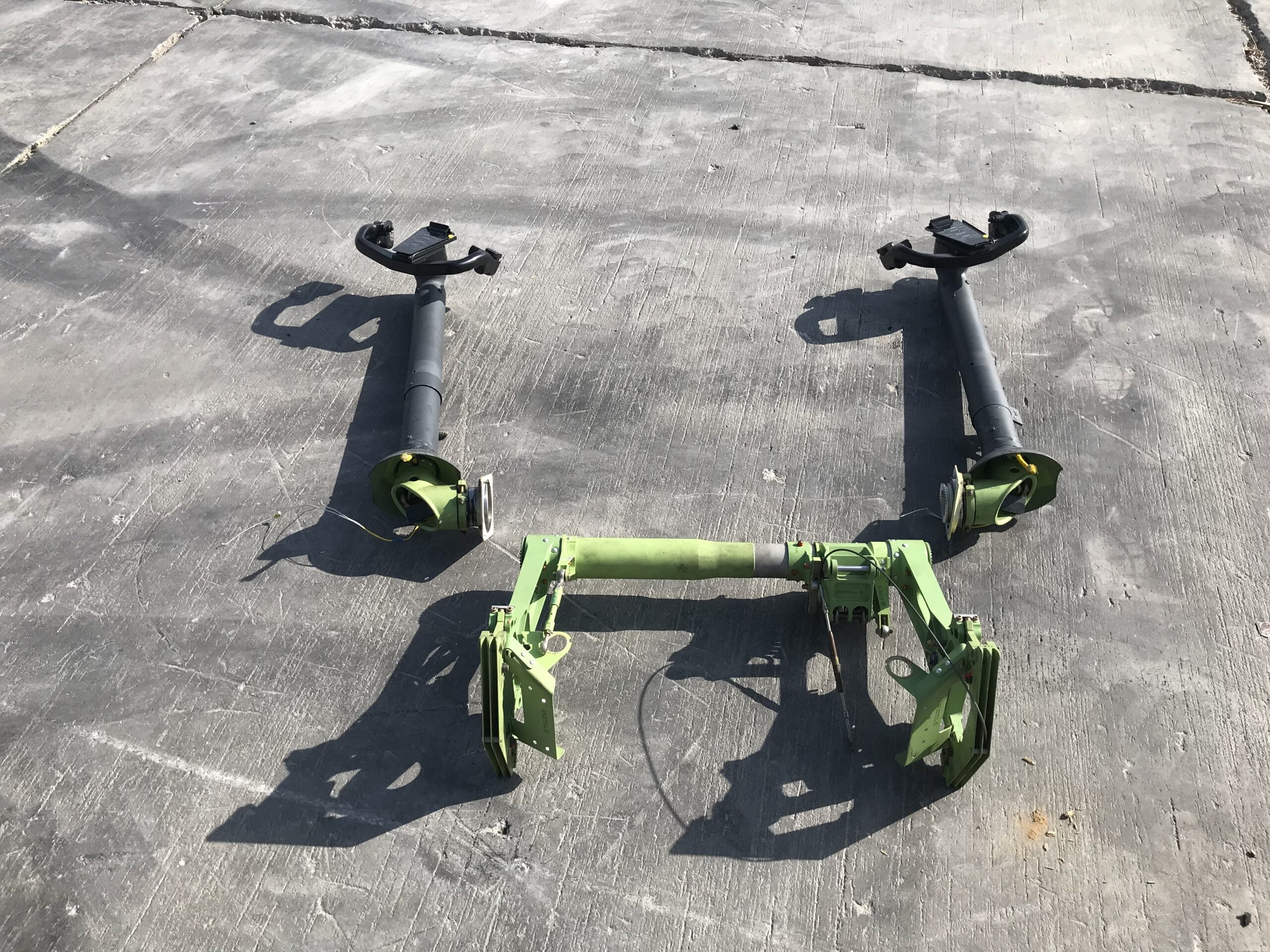
The Starting Point
Fortunately, after a stroke of luck a couple of years ago, I found some excellent condition original equipment (OEM) control columns and a cross-tube at a very reasonable price from a just scrapped Boeing 737-700. I jumped on them, figuring I’d eventually put them to use with my own linked column solution. Now, it was a matter of figuring out how to put them to good use to meet the goals above.
Challenges Building my Control Columns
For a long time the control columns just sat around gathering dust as I had been putting off the project knowing the amount of work would be significant.
As I thought more about it, I realized in addition to coming up with a design for robust mechanics, a feat unto itself, I’d have to create an entirely new base/floor structure to accommodate the columns as my previous base could not be modified. This meant eventually the entire cockpit shell would have to be transplanted to the new base. Considering all the wiring, panels, seats, etc that would have to be removed and relocated (not to mention the headaches of getting it all working right again), it quickly became overwhelming.
Another challenge I faced was the height of the cockpit floor/base. Generally, linked control column mechanisms are under the floor as in the real aircraft, so you need enough space beneath to house the components. It’s typical to have a minimum 16-inch high base when you have under-floor linked columns. Unfortunately, my collimated display structure was designed for a specific cockpit height, and the cockpit bulkhead was also designed for a specific cockpit floor height, so I was basically locked into the approximately 12″ base height I already had. That meant whatever linked column mechanism I went with would have to be pretty compact.
Alternatives to DIY Control Columns
So, rather than reinventing the wheel (pun not intended), I first looked around at some compact third party dual-linked column options to save some time and brain power coming up with my own solution. These solutions are obviously already well engineered, time tested and ready to drop in, potentially saving a lot of headaches.
Here’s what I found:
- Simujabs (in Spain, I believe) had a very nice compact linked setup for around €3.5K and was the front-runner until he sadly went out of business right before I decided to buy. He would even take real columns and adapted them to his frame, which would have been ideal for me.
- Agronn (in Turkey) was next in line with their Dual Yoke Type D at around €4K. It’s a nice, compact, seemingly well-built and reasonably priced unit but when I started asking about the capability to add my own future control loading (aka force feedback), they mysteriously lost interest. It’s too bad as I was ready to pull the trigger on it.
- FSC (Italy) has one of the nicest and probably most robust linked column setups that is also control-loading ready, but the €8K price was just too steep for me. Don’t even ask how much they charge to add their loading solution. But, if money were no object, this is probably the route I would have gone.
As a side note, I personally own the pricey FSC linked rudder pedals and I love them. They are built like tanks and well-engineered so you do get a solid product for the money. Sadly, their pricing is more geared for flight schools and businesses which I believe is their real target audience, so their products are often out of reach for the average simmer.
Unfortunately, none of those options worked for me so I was left with two choices. “Do or Do Not. There is no try”. Obviously we’re going with “Do” and designing my own solution.
Starting my DIY Control Column Design
The extra push I needed to dig in and seriously start my own build came from my friend Fabian Betancur, who had designed and built a similar linked control column setup, but also added his own custom control loading solution. He even wrote some open source software called ACL that makes it much easier to interface a custom control loading solutions with Lockheed Martin’s Prepar3d or Microsoft Flight Simulator. The addition of control loading was an exciting prospect so I decided to include it in my build as well. With his project as a reference, and his experience to guide me, at least I wouldn’t be starting from scratch.
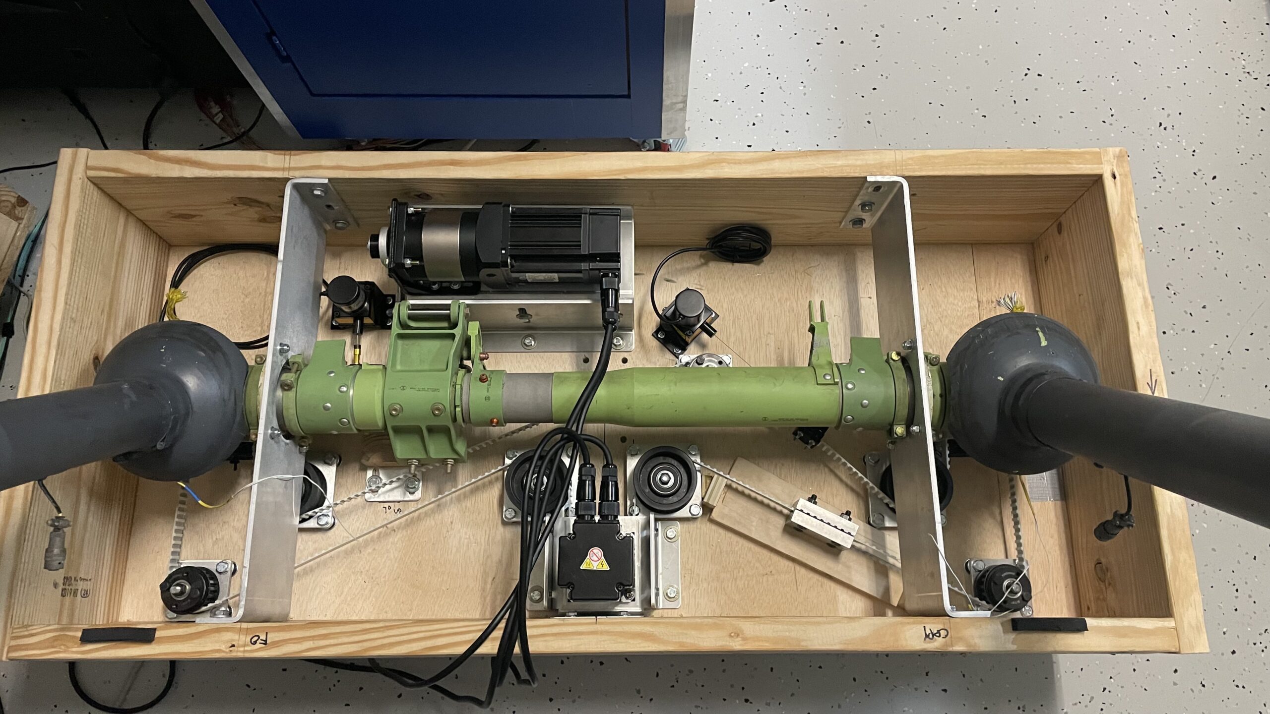
Note of thanks: While you'll see my build has turned out quite different from Fabian's in many respects, my generous thanks go to Fabian for his inspiration, knowledge and helpful hand along the way! It's people like him who blaze a trail the rest of us are lucky enough to follow. Make sure to check out his *REAL* 737NG sim conversion. It'll blow your mind!So, the overall design concept for my project looks like this:
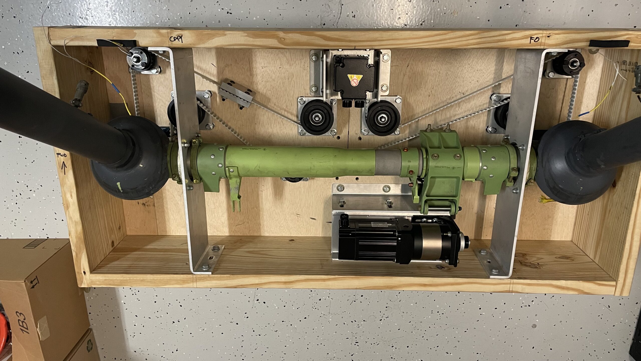
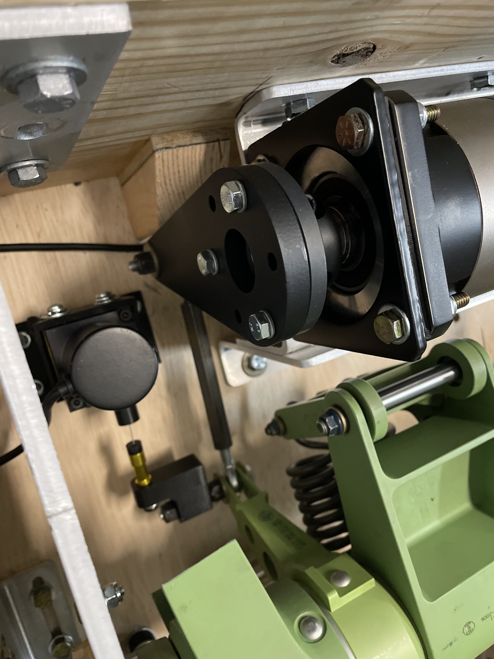
Pitch Axis: A heavy-duty NEMA motor, driven by an A/C powered Servo Driver (control box) connected to a heavy duty 50:1 ratio planetary gearbox that has an A-arm connected to its output shaft. The A-Arm connects to an arm on the center cross-tube via an adjustable ball-end linkage. As the motor moves the A-Arm, it drives the linkage to rotate the cross-tube, and hence move the columns forward and back. A heavy duty planetary gearbox is needed due to the long moment-arm of the column which would easily overpower the motor/gearing due to the high torque. A string potentiometer is connected to the cross-tube arm to pass the column position values to the simulator.
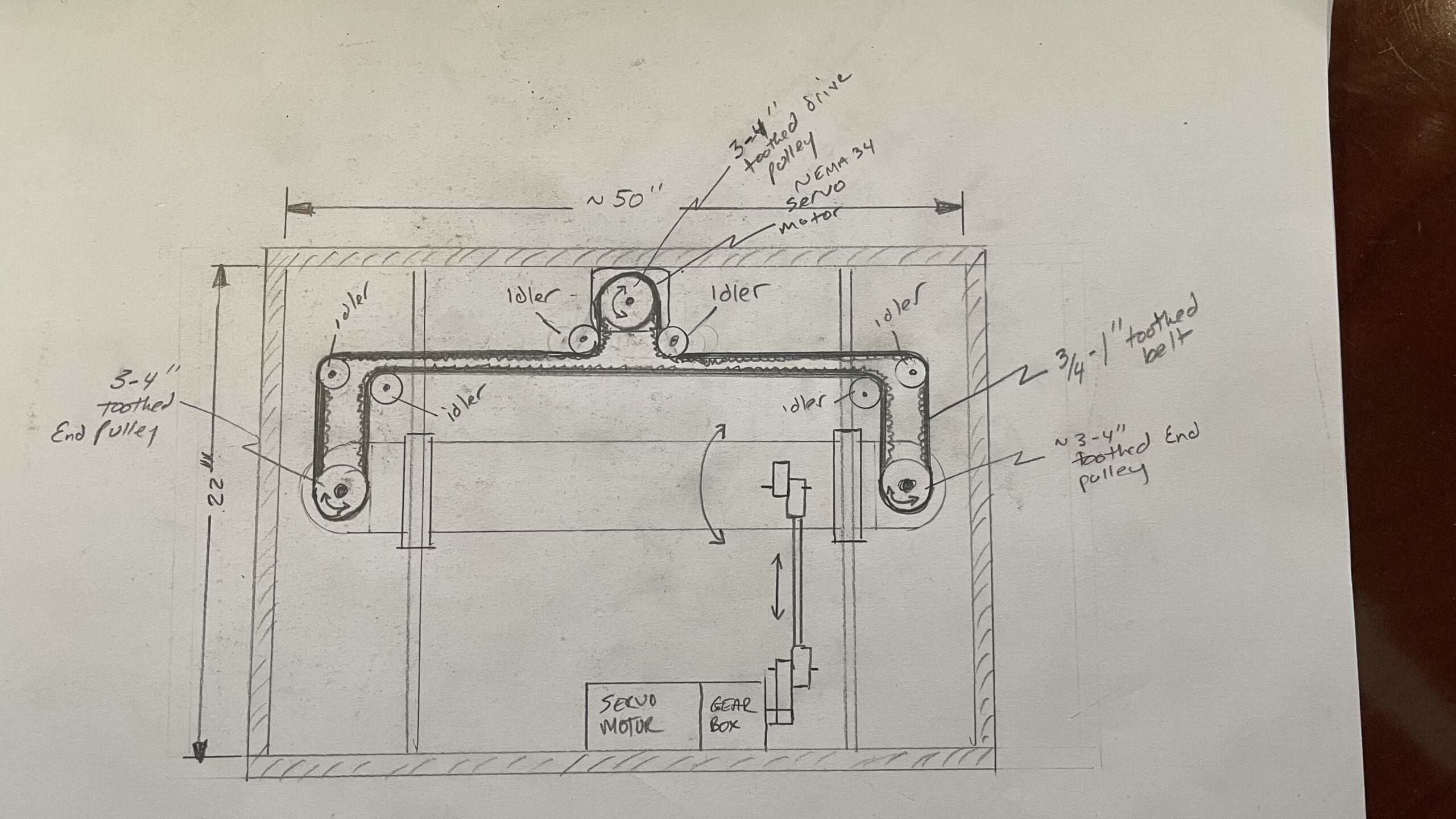
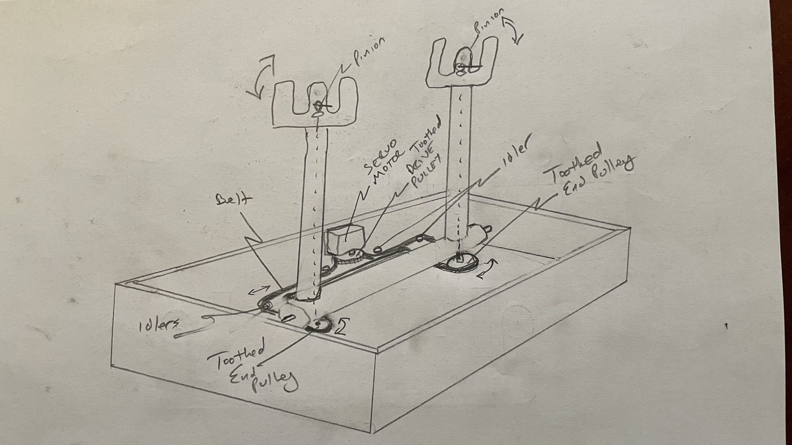
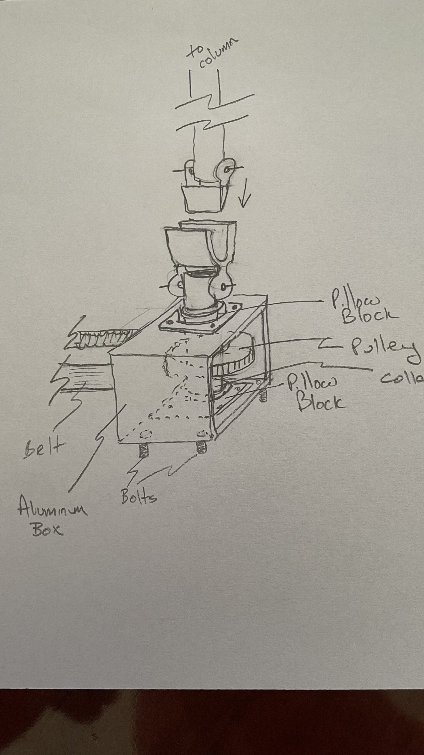
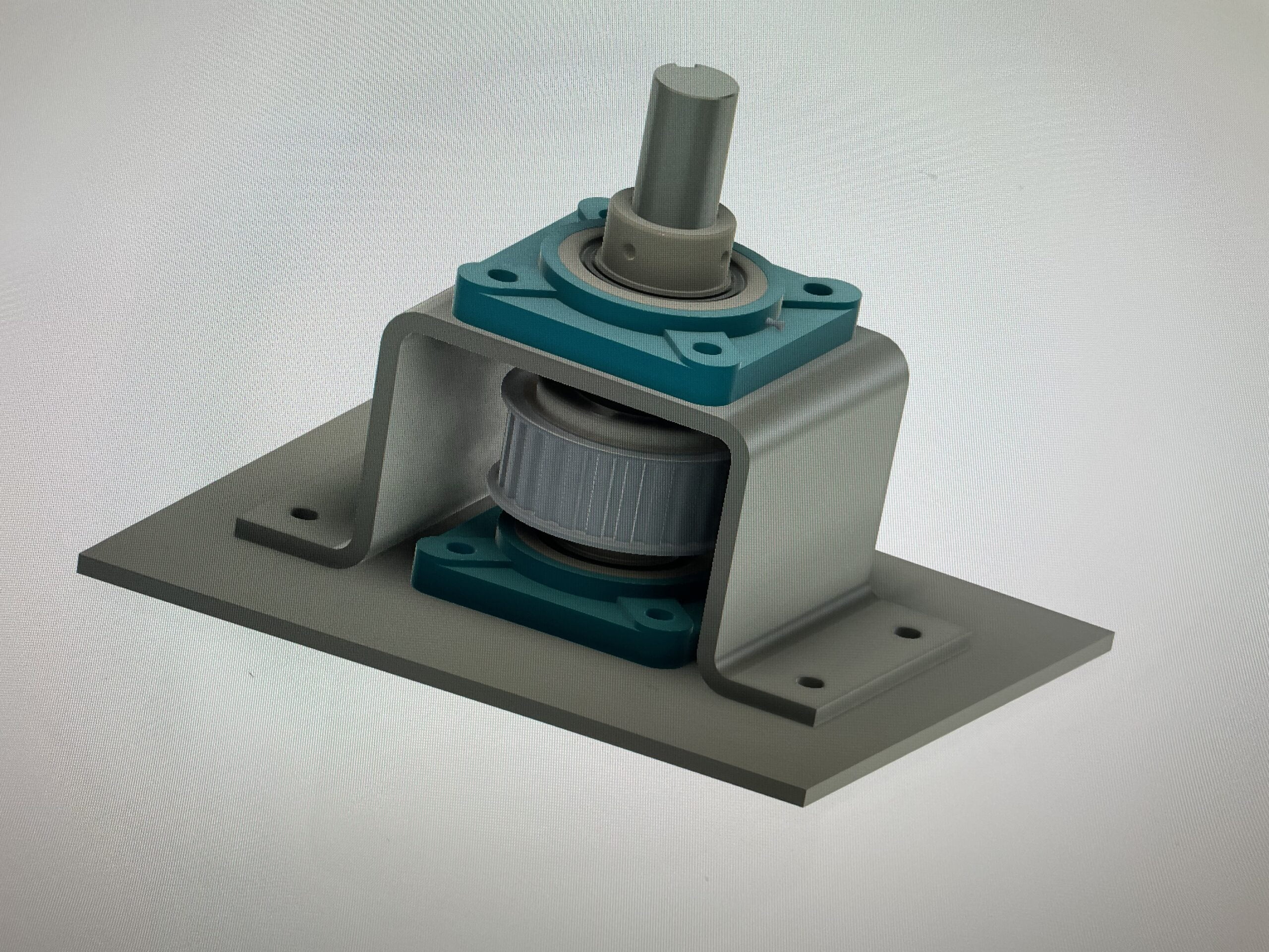
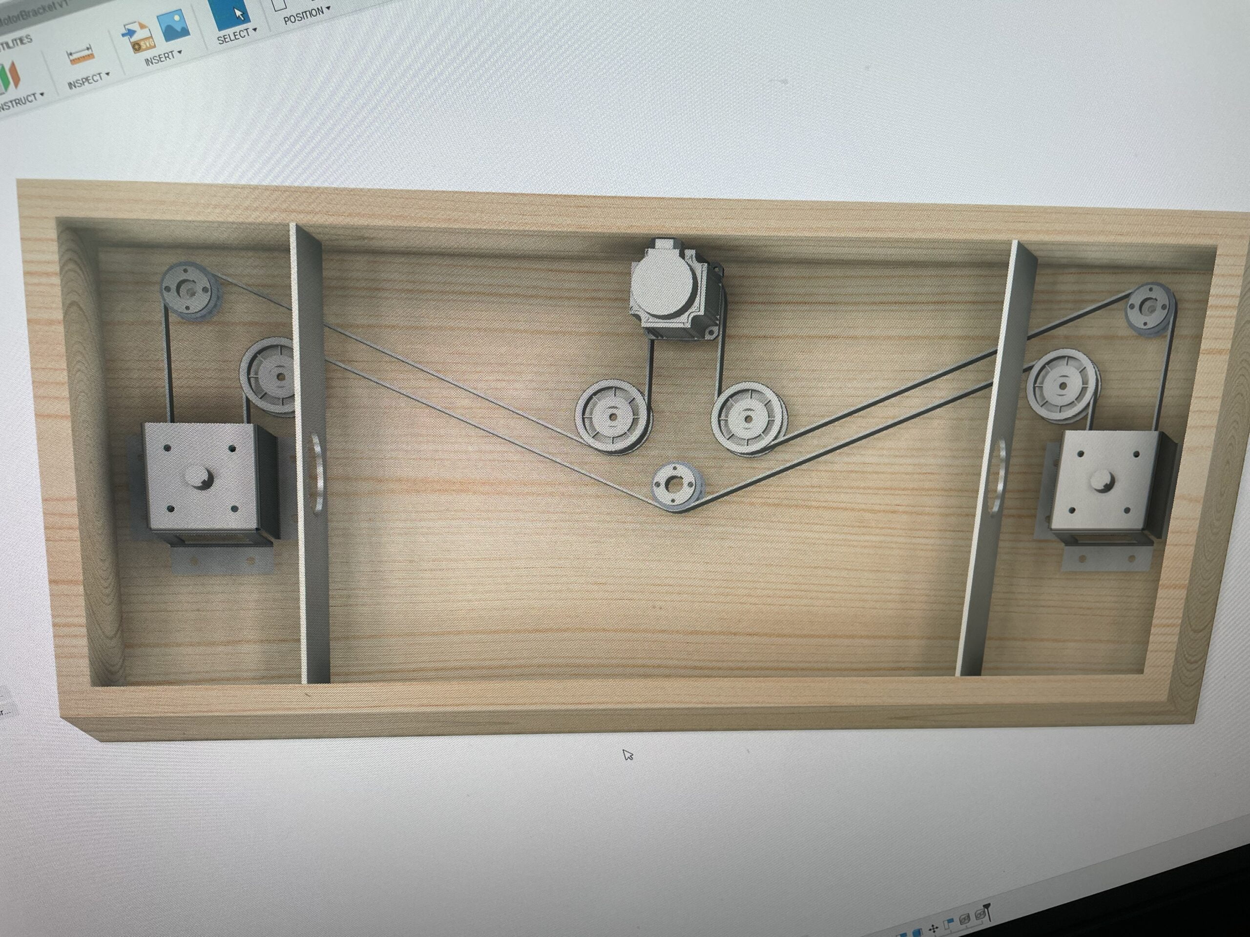
Roll Axis: A heavy-duty NEMA motor, driven by an A/C powered Servo Driver (control box), will have a keyed toothed drive pulley directly mounted to its motor shaft, and a toothed belt that runs directly from the motor pulley, around some guide pulley’s, to a keyed toothed pulley under each control column. The control column pulley drives a vertical shaft that connects to an OEM spade connector (essentially a universal joint) which is then connected to a shaft that runs up the center of each column to drive the respective control wheel. As each control wheel is rotated, it rotates the associated pulley below via the drive shaft, driving the toothed belt connected to both the motor and the other control wheel. This also allows the motor to add resistance to the wheel movement, as well as rotate the control wheels while on auto-pilot. A string potentiometer is connected to the belt to pass control wheel position info to the simulator.
Software: I will use Fabian Betancur’s open source ACL software to control the movement and forces of my control column setup.
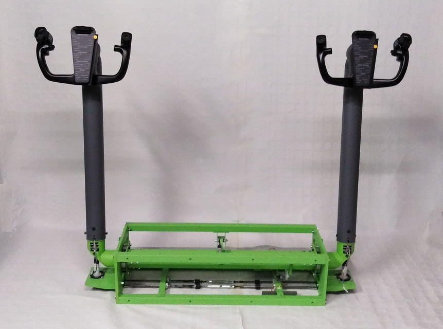
More detail below, but here’s what it basically looks like in a 75% complete state:
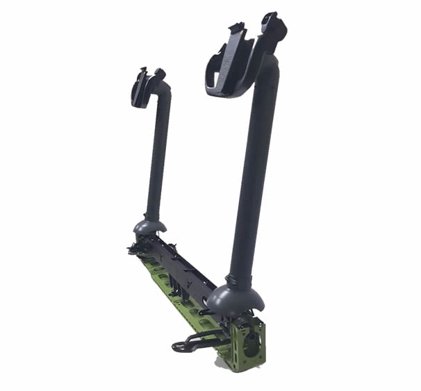
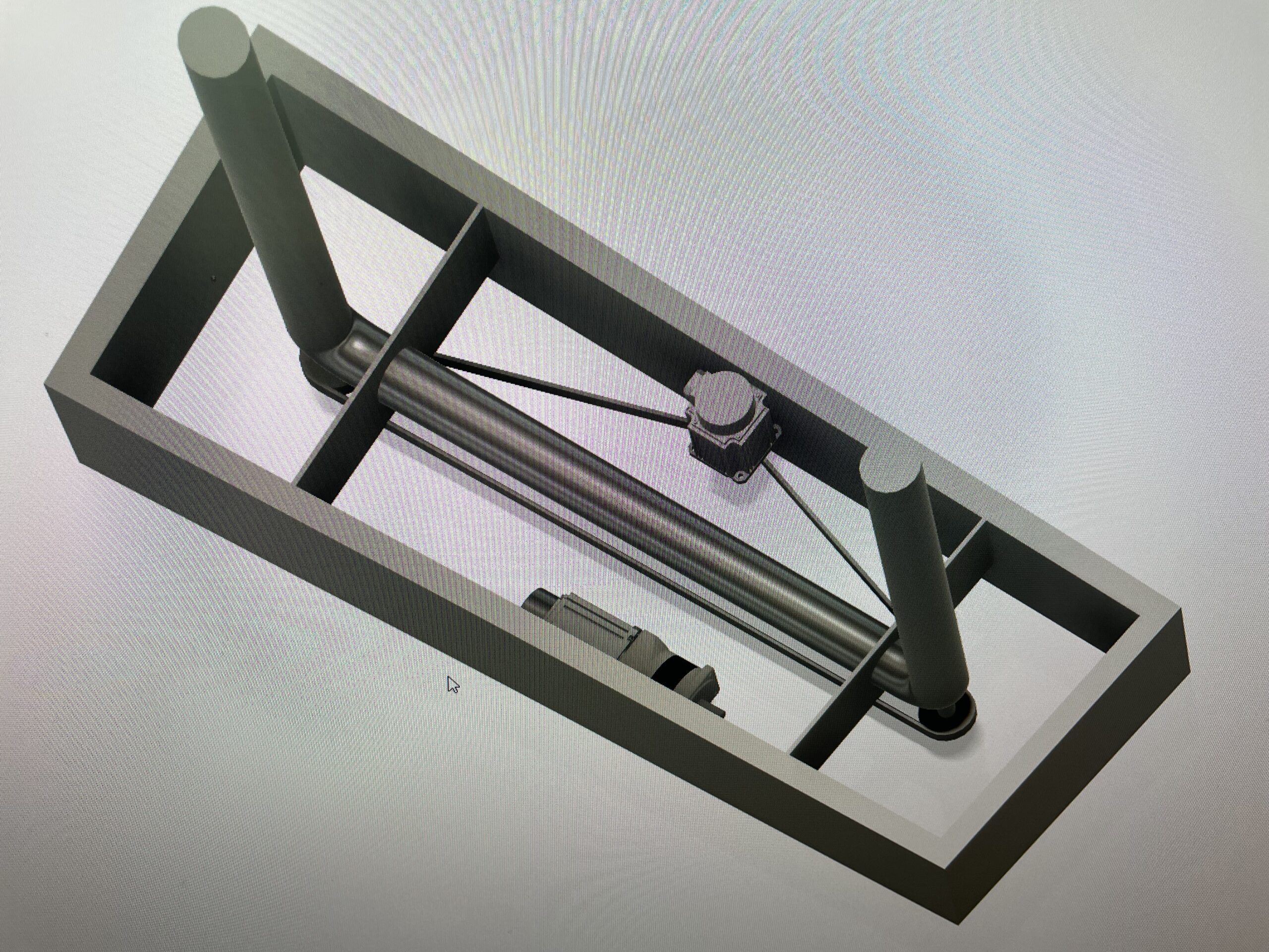
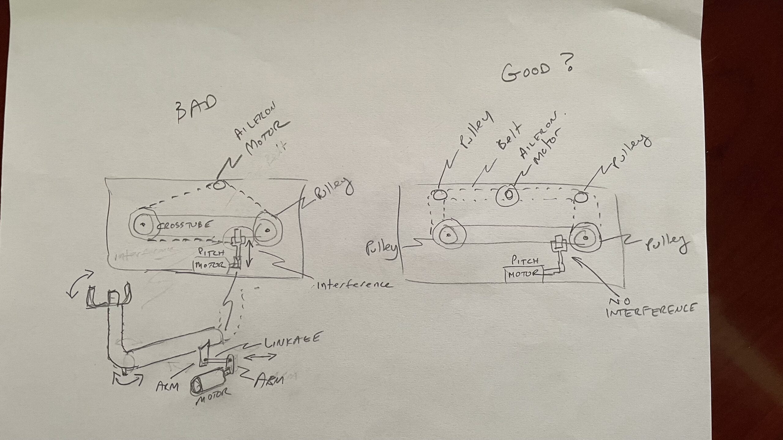
Concept Drawings
Below are some of the design concepts I explored while I brainstormed linking the columns along with adding control loading, based on Fabian’s motor specs. The final picture is the approximate design I ended up going with.
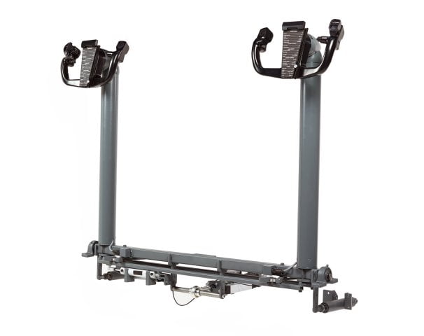
Progress Photos
Here you can see some photos as the build progressed:


To be Continued…
Due to the length and time it takes to put all this down in writing, and that I’m still tweaking and testing, I’ll have to break this up into parts. I’ll continue the discussion in Part 2 where I’ll talk more about the building the Support Structure and Pitch Axis.
>> Next Up – Linked Control Columns & Loading – Part 2 – The Pitch Axis


2 comments
Absolutely awesome. Very well done… Looking forward to see more on your progress.
A very useful documentation. Looking forward part 2 😊