
Last Updated on June 1, 2023
Got a few more things done recently as more major components are coming together.
STEERING TILLER
I had bought a new Flightdeck Solutions (FDS) spring-loaded steering tiller a while back but had nothing to mount it to so it just sat in the box. Now that I’m getting to the point I’m flying the sim more, steering with rudder pedals just wasn’t cutting it. If I recall, you only get about 7 degree max nose wheel deflection with the rudder pedals and the rest of the deflection coming from the tiller. If I didn’t want to continue making these giant lazy turns, it was time to at least temporarily mount the tiller.
With some cheap 2×4 lumber I had lying around, I slapped together an ugly support stand for the tiller that put it at close enough a location that I now I have something usable. And let me tell you, it makes a HUGE difference steering the aircraft on the ground.
Here’s what it looks like:
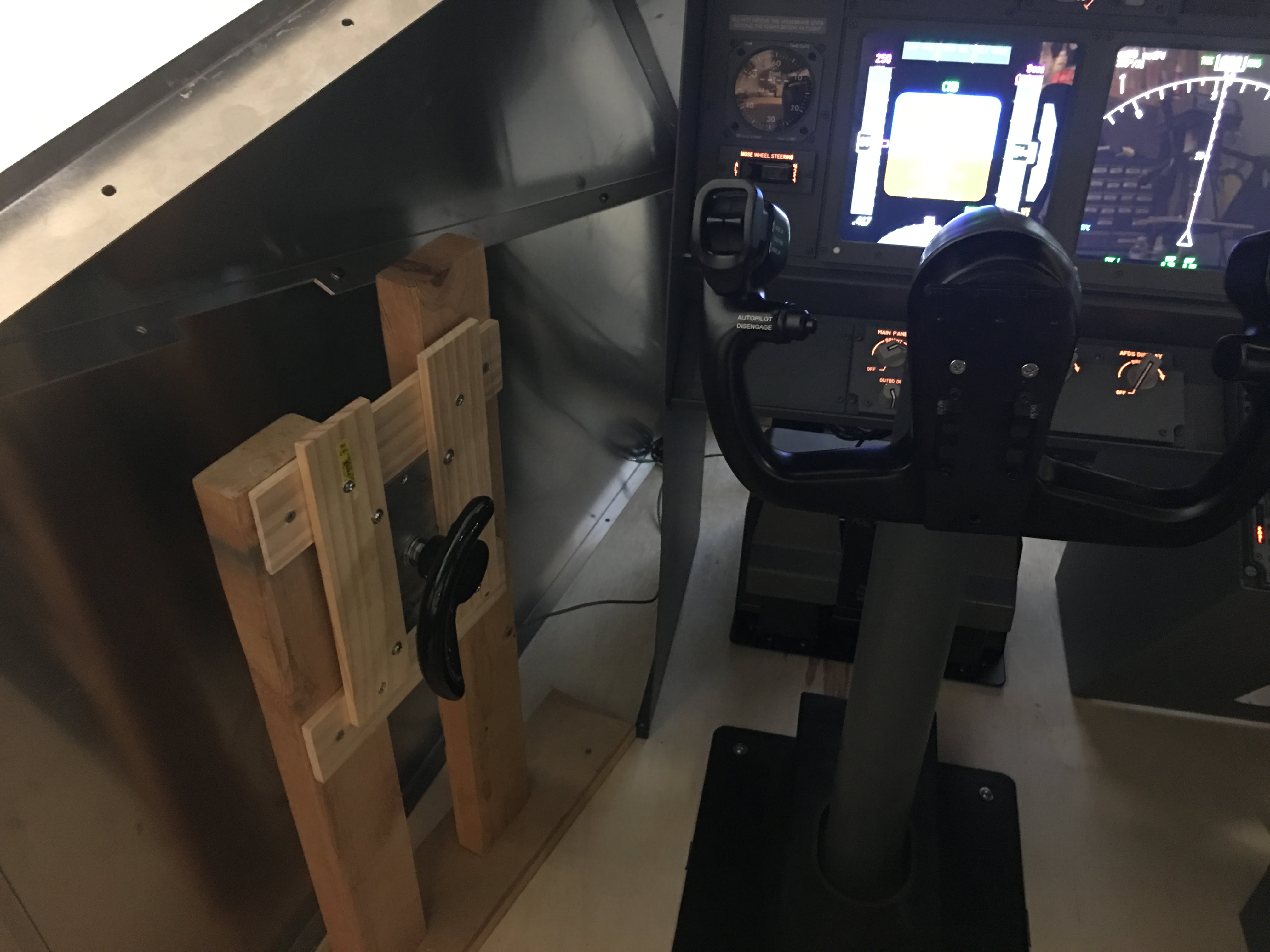
Told you it was ugly! I didn’t even waste time trying to trim everything evenly, lol. I just wanted something there for the time being. Hey, it works, and it works well so don’t judge!
LOWER EICAS
I recently purchased a FDS lower EICAS screen so I can display my Engine and Systems displays during startup and controls checks, and fill the empty looking void that was in the middle of my lower MIP.
Many people opt to buy an inexpensive TFT monitor and mount it all themselves. More power to them and they’ll likely save some decent money since this kit was somewhere around $350 USD. Ouch! But for some projects, in my mind, sometimes the cheaper way isn’t always the cheapest in the end when you factor in time, effort, more parts you’ll inevitably need, and mistakes you make along the way. Everything I needed to make this work perfectly with my FDS Main Instrument Panel (MIP) is in the kit and you’re up and running quickly with time to focus on more important things.
So the kit is basically a 16×9 screen kit that perfectly fits the horizontal space between the CDU bays. But because of the 16×9 ratio, it’s longer top to bottom and protrudes out the bottom of the bay about an inch and a half or so. This is fine since the FDS bezel that came with my MIP covers over the entire thing nicely.
Not many parts. A couple of clear plexi side mounts, the main screen, a plexiglass mount board that sits under the monitor that has all the monitor electronics already mounted to it (very nicely done, by the way), and some bags with necessary screws, nuts, retaining springs, and miscellany. Everything was beautifully packed as usual. Always impressed with how carefully they package their parts.
I’m not very good about remembering to takee unboxing pictures (need to work on that) so I’m sorry I don’t have much useful to show of the contents of the kit.
Installation was pretty straightforward. Followed their instruction manual I found in their manual repository and it went something like this: Mount the plexi side rails using the longer replacement DZUS rail screws for the left/right CDU bays, drop the plexi electronics board into the bay and secure with the included double-sided tape, connect the wires from the electronics board to the monitor, slide the monitor up into the space created by the plexi rails, then retain in place using the included springs. Lastly, double-sided tape the FDS MIP bezel to the sides of the monitor and connect a monitor cable (not included) to either the VGA or HDMI inputs on the electronics board.
Only issue I had was the wiring between the electronics board to the monitor were too short to allow me to slide the monitor up from below. I had to bend the CDU bay walls a bit to make enough separation to angle in the monitor then press the bay walls back into place. Not as elegant but it works.
Once I had the monitor hooked up to my Avionics PC it showed up like any other monitor in Windows. Then I created a new Prosim Display to show only the lower EICAS and dragged it over to appear on the new monitor. Easy peasy.
Here’s what it turned out looking like:
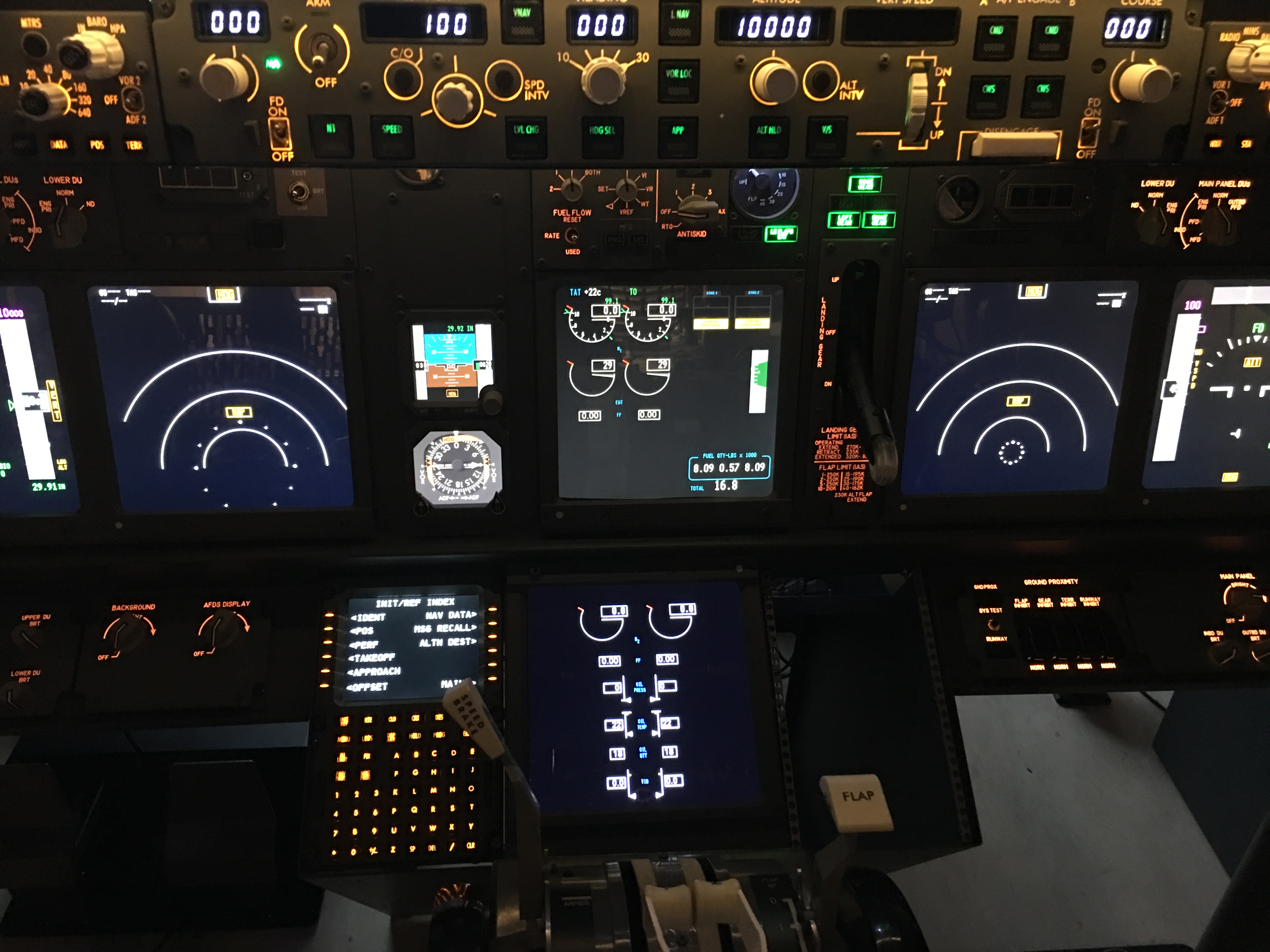
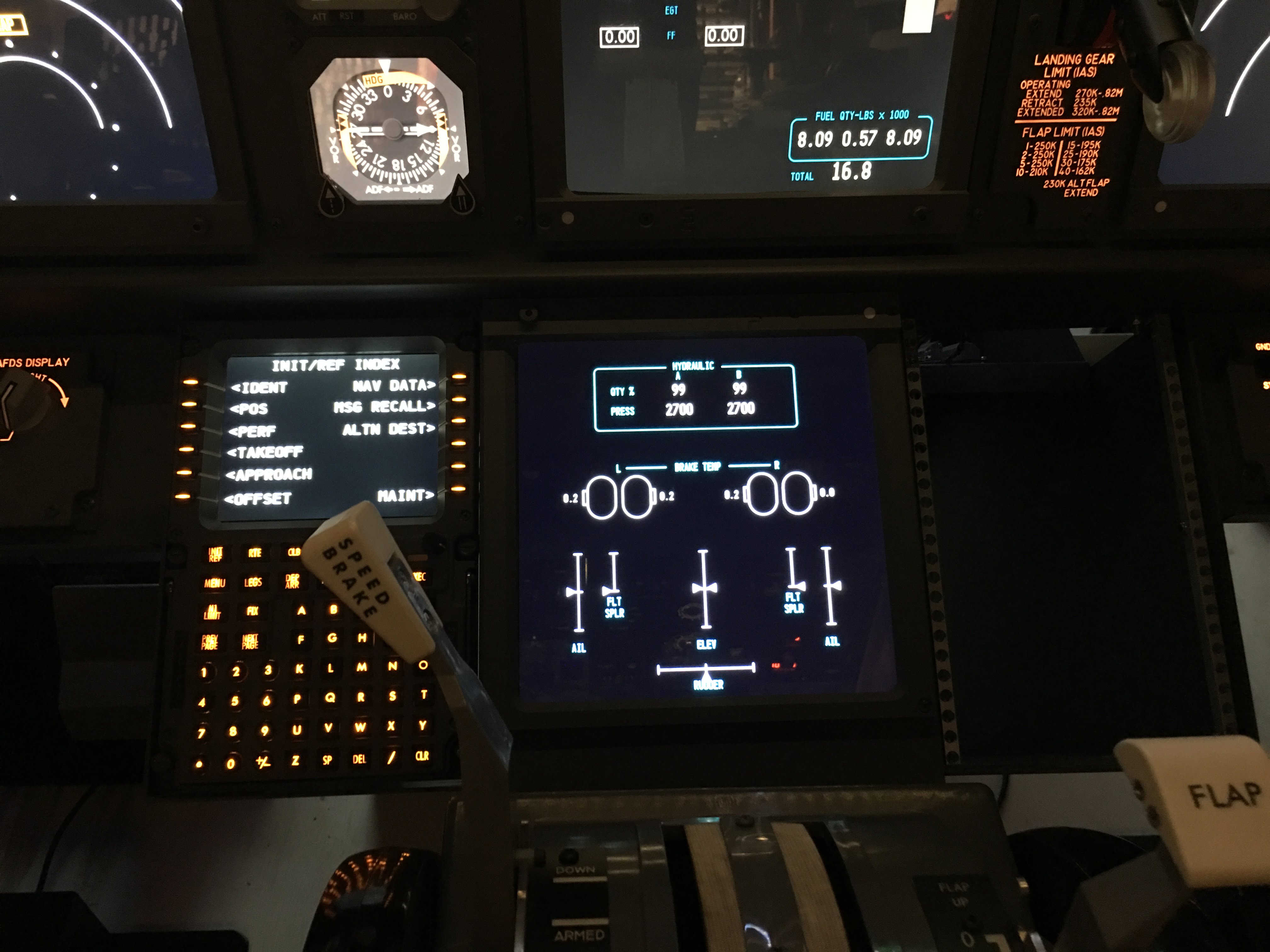
It works with my Lower DU switch such that I can move the Navigational Display or Engine display over to the lower EICAS screen with a turn of the switch, and using my MFD display buttons, I can vary what I display…either Engine output as seen above with the ENG button, or the Systems display with the SYS button as seen below:
AFT OVERHEAD
This has taken a lot longer than I anticipated, even though it’s way simpler than the FWD Overhead which took a couple months of almost daily labor (mostly wiring). The CockpitSimParts components I bought, while fine, would have resulted in even more time and effort recreating certain things than I wanted. So I have been spending time sourcing and waiting for some pre-built modules to save time and effort and achieve a better end result. I ordered several modules from SISMO Soluciones for the AFT: the LE Devices indicator, the IRS panel (discussed here) and the Audio Comm Panel (ACP) which arrived today. That last piece, plus the servo card I was waiting on to power the sole servo gauge in the overhead, were needed to allow me to start finishing up the rest of the panel.
I decided to order the Sismo ACP because it was reasonably priced and had more functionality than many of the others seemed to have, even though I’ll probably never use the ACP in the AFT Overhead. It’s more for looks to be honest, but also a gauge to see if maybe I want to buy the same ACP’s for the pedestal at a later point (I’ll need two).
So maybe a week ago the AFT panel looked like this:

Already looking pretty good. All switches and indicators are working except the Audio Panel (CockpitSimParts dummy) and the gauge (fully functional but not connected yet).
I mounted the new ACP today and here’s what it looks like in:

Looks much nicer, doesn’t it? I have yet to hook it up to a secondary SISMO GIC v4 card and get it interfaced.
I have some thoughts on this panel and the LE Devices panel which I’ll hopefully include in a future update once I’ve had more time to play with them and clear up my thoughts.
What’s left? Aside from hooking up the ACP, I need to get the servo card hooked in and operating. I also need to swap out all the screws with more realistic looking DZUS replicas. And while there’s not a ton of wiring in this one, the Sismo ribbon cables tend to make a mess of things (wish they had a better “BUS” between cards that wasn’t so bulky) so I need to try and organize that better.
I’ll take an internal shot once I have it all wired up so you can see how it went together.
PEDESTAL
Ah, this one has been fun!
I was looking at simulated Fire Suppression Panels (FSP’s) at the various sim parts makers for a while. You know the panel…the one with the three red handles at the top center of the pedestal, just after the throttles. It looks like this:
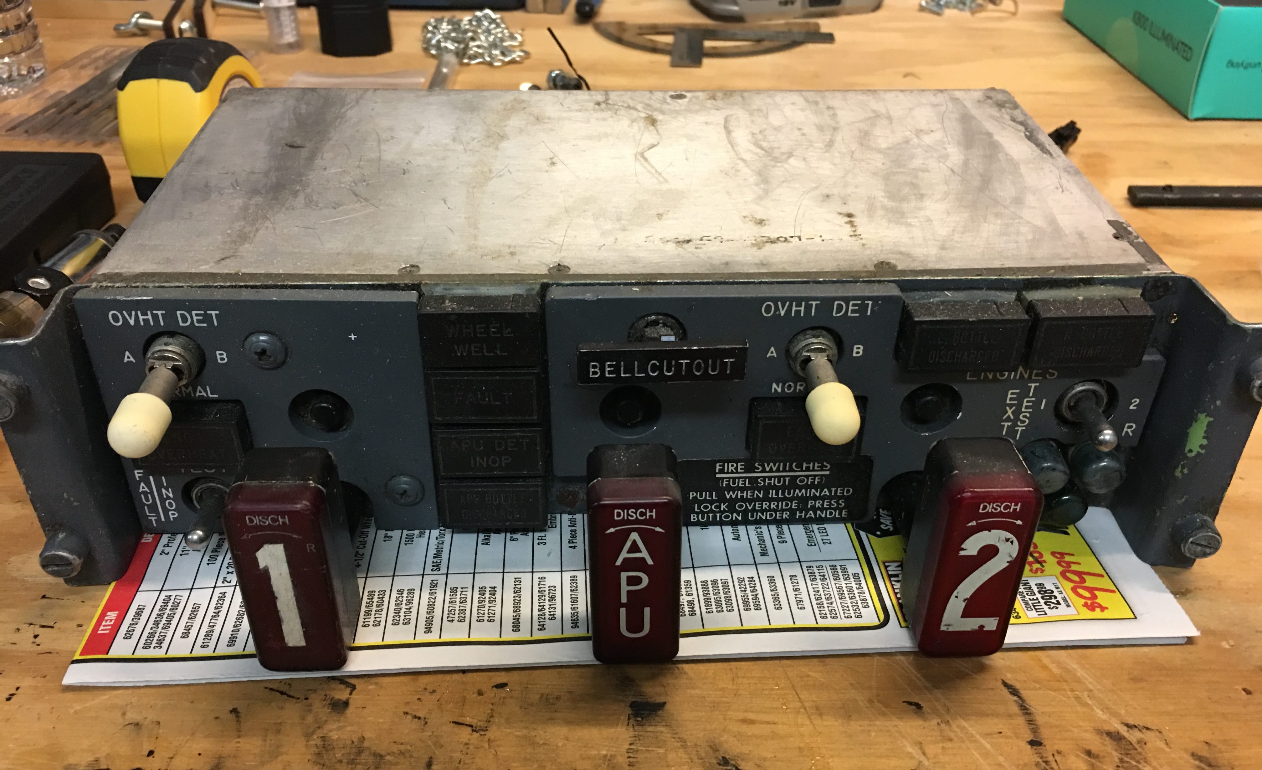
This is obviously one of the most critical components because it helps you identify if you have an engine fire, which engine the fire is in, and give you the ability to try and extinguish it. Obviously a pretty important piece during simulated fire and engine failure situations.
But the cost for the replica panels made by the major sim components companies was pretty high. And with something that I hear takes a bit of abuse, I’m not sure how well a simulated part would hold up compared to the real thing (I can hear all you real-parts purist guys shouting from the back row..THEY DON’T!). Problem is, I had no idea how to convert something as complicated as this to work with a sim. So a bit of a pickle.
That’s when a fellow simmer I know who uses almost all real parts said “I know a guy who does these conversions…he did mine, he might do one for you.” I was immediately intrigued. Turns out this guy is also a real 737 pilot, a super nice guy, and does this in his spare time. After we had a great call (could have picked his brain for days), we agreed he would convert, for a fee, the real FSP I had just procured on eBay at a great price and in great condition (see FSP pic above). While his fee is not cheap, it included his labor plus all the necessary parts and pieces to convert. That was a no-brainer for me. I was more than happy to oblige since the cost to convert plus the cost of the FSP would work out to the same as a simulated panel. And I sure as heck didn’t know anyone else who’d take this on.
Unfortunately plans changed and funds dried up as we decided to move to a new home, so it took a lot longer than planned. I recently contacted him again and said I was absolutely ready to go this time so let’s do it. I shipped the FSP off to him and like Superman, he had the thing done in what seemed like the blink of an eye. He had everything working, from the solenoids that lock the fire handles to the push to test indicators, to even the three green “Squibs” (the little green circles at the lower right of the panel that verify the extinguishers are charged), and all the switches. Unbelievable.
I got the unit back about a week ago and realized my home made pedestal isn’t ready to mount this thing properly. I wanted to swap out my wood rails with true DZUS rails (rails that have the mounting holes pre-drilled and a metal wire running down the center of the holes where DZUS fasteners can lock onto and secure panels in a simple 1/4 turn of a mounting screw). In the long run I knew putting in these DZUS rails would make mounting and maintaining future panels much easier so I set out to find a place that sold them for a reasonable price. I located an Aviation supplier in Dallas, called them up, and the next day I had the needed lengths of right angle and T DZUS rail ready to be put in.
Next challenge was cutting these down to size to fit the pedestal properly. I eventually just picked up a decent metal hacksaw at Home Depot, threw the DZUS rails in a vice and cut away the lengths I needed, trimming off the burrs with a regular vertical sander. These are made from aluminum so they cut and sand very easily. Just make sure you wear goggles so your eyes don’t get hit with metal scraps, and wear a respirator just for safety sake.
Once the pieces were cut down to size I had to figure out how to fit them into the pedestal, which I had originally made out of MDF.
The 90-degree DZUS rails for the sides were easy. Just screw them into the sides with small screws every so many holes.
The T-Rails I used in the center section of the pedestal were a bit tougher. The easiest solution I came up with was buying some small 2-hole 90-degree brackets at Home Depot, drill a hole in the T-Rail at both ends, and run a screw through two of the 90 dgree brackets and put a nut on the end. This essentially made a vertical T at both ends that I could then screw into the front and back walls of the pedestal.
Maybe this picture will help explain:
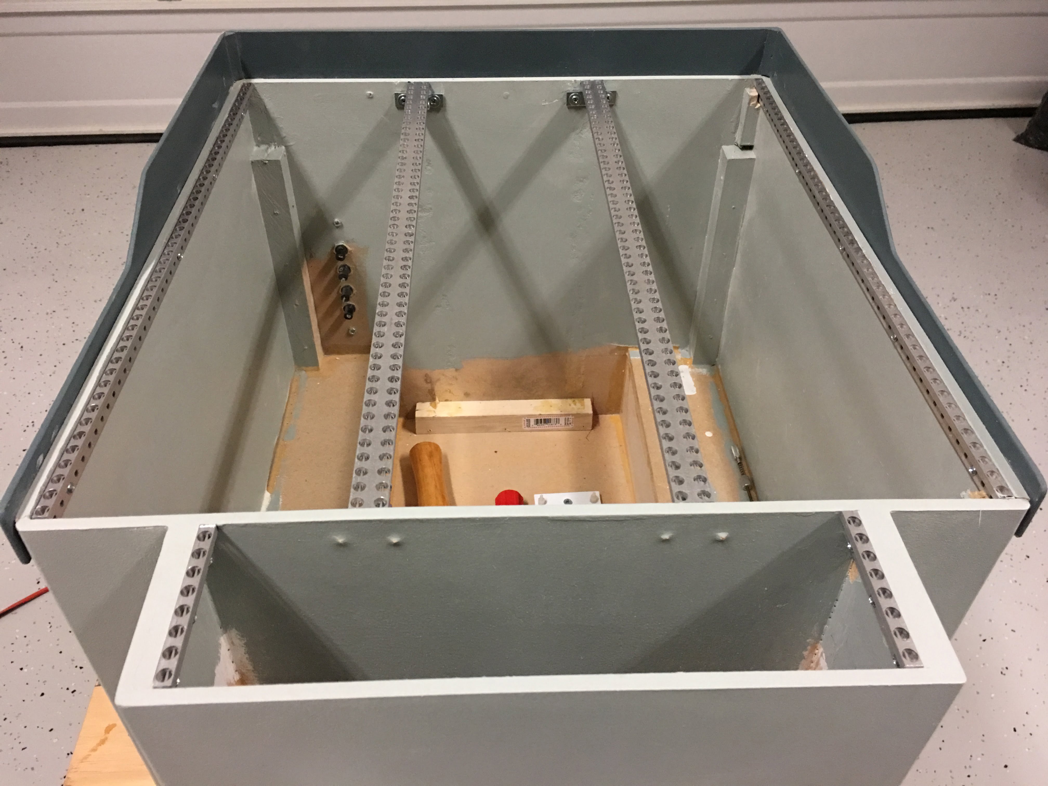
Turned out to work quite well and it’s very sturdy. I did run into a rail spacing issue. I knew I already was close because the original rails I made out of wood were exactly the same widths as these DZUS rails, but for some reason, my main pedestal panels just didn’t quite drop in the holes so I had do so some shimming with some washers on one side to shift things a little.
And yes, before you say something, I know the Fire Panel bay is too wide. I used many conflicting Internet measurements to determine an “average” for some things, and this was one that unfortunately was way off. I didn’t feel like redoing it when I put the DZUS rails in so I just made some minor mods to the spacers on either side and was done with it.
Here’s what it looks like with the panels I have mounted:
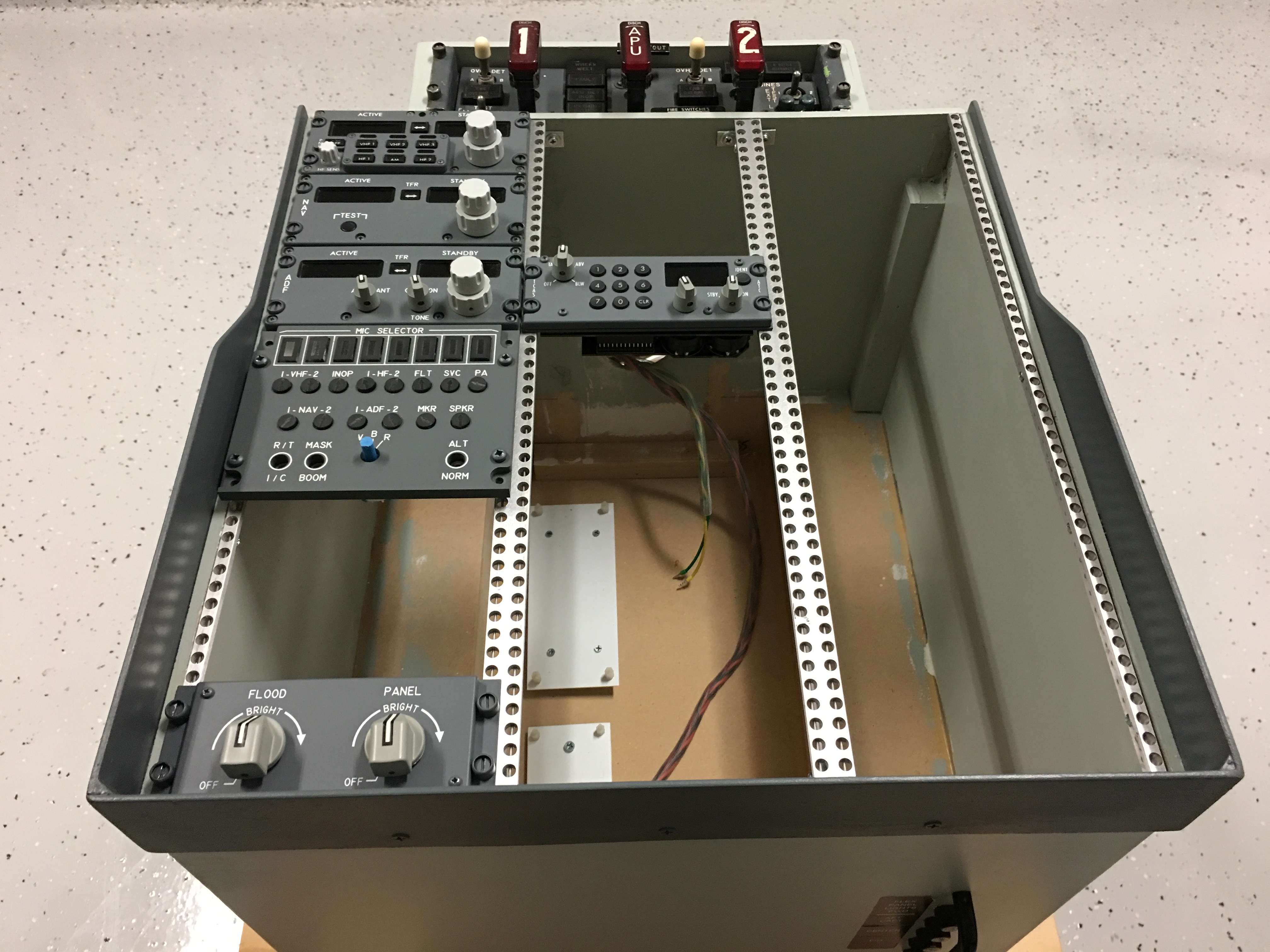
What’s left? I still need to put back in the FDS Ethernet module and reconnect the few Flightdeck Solutions Ethernet panels you see above. I’ll have to also reconnect the FDS lighting board to the light panel at the bottom left in the pic above.
Will then install the 24 Volt power supply that will power the FSP. It actually runs on 28 Volts, which is normal aircraft DC power, but 24 Volts is sufficient I am told. This will ensure the relays operate properly to lock the fire handles, and other various higher voltage items will work. The way it has been configured, there is one USB input so that just goes into the avionics PC and ProSim will pick up all the various indicators and switches as if it were a simulated part. Very cool!
Then I think I’m going to start playing with the inexpensive CNC router I bought to try and make blanking panels to fill the spaces in the pedestal. Over time I’ll fill many of those spaces with the remaining panels needed. It’s certainly an expensive hobby that doesn’t usually happen in a day unless you’re a millionaire or have been saving for a LONG time to do all at once!
CLOSING
Well, it’s late, so I’m probably not making much sense by now. If you read this far, thank you. I hope it was at least a little helpful, if not entertaining. Until the next update, take care and good luck with your project!


Hi, if you mean the two rails that run from front to rear and the cross strut, yes those came…