
Last Updated on March 7, 2020
As you may have seen from my Throttle Quadrant (TQ) page I am rebuilding my Revolution Sim Products TQ which I bought second-hand (or maybe third-hand, fourth-hand, who knows) . It’s a complete tear-down and rebuild from almost bare bones. The internals were not in good shape. Pieces were broken and glued back, screw holes were stripped, the auto-throttle automation was iffy at best, and the software was so outdated that some critical functions (fuel selector, for example) didn’t even interface/work anymore.
It was not something I wanted to do, nor even knew how to do, but I wasn’t satisfied and since I can’t afford to invest in a $5K+ motorized TQ replacement right now I figured I’d try to fix this one. The basic structure is there. Maybe with some TLC and proper fixes maybe I can get it to work right yet.
Since you can read and see more of the tear-down on my Throttle Quadrant page, I’ll focus this post on rebuilding the Auto-Throttle mechanism.
Original Auto-Throttle Design
The original design driving the throttle levers used a stretch of upside down toothed belt with the ends of the belt fixed around a big gear wheel that the throttle lever was attached to. The belt was then also wound around a fixed tensioning idler pulley and a drive motor pulley. The smooth side of the belt faced the pulleys allowing the belt to grab the drive pulley just enough to move the levers, but also just enough to slip (like a slipper clutch, so to speak) when you moved the levers manually against the auto-throttles (not sure why they used a toothed belt but the teeth weren’t used).
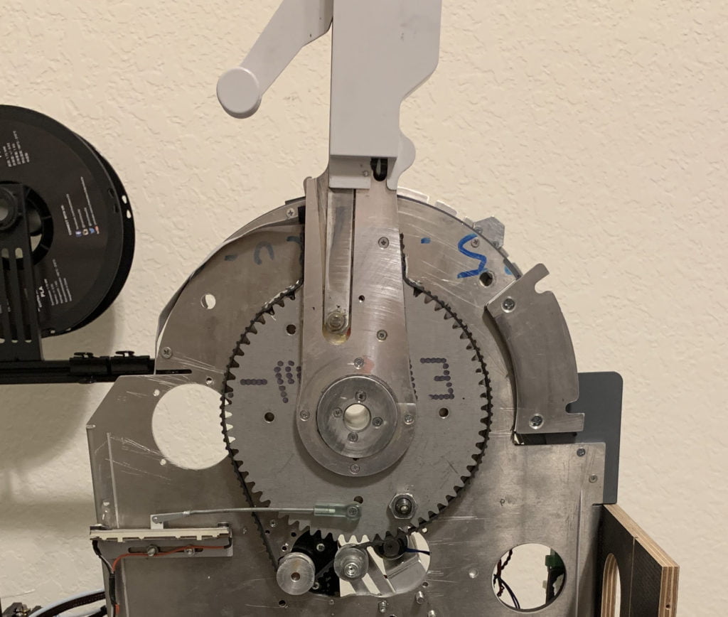
The original TQ Throttle Lever Drive Mechanism – An upside down toothed belt screwed in at the top and wrapped around a fixed tension idler and a drive motor pulley.
There are some problems with this design in my view:
- It’s not easily adjustable to get the right amount of tension in the throttle levers
- Once the belt is grabbing correctly, the TQ handles become much too difficult to move in order to override the auto-throttle
- Loosening the belt to reduce force necessary to move the levers against the auto-throttle motors meant the belt sometimes wouldn’t grab enough and get “stuck” without a manual nudge…there was no in-between
- The belt could stretch over time making the reliability poor
- The idler pulley mounts were stripped so maintaining proper belt tension was inconsistent
My Solution
I decided I needed a more reliable and consistent method of making the levers move, something I could set and forget.
I envisioned getting rid of the drive belts and instead mounting a spur gear on the drive motor which then meshed to the larger gear attached to the throttle levers. This would ensure a solid connection to the motor. But how could I get the throttle levers to slip against the drive motors when you need to override the auto-throttle?
Enter The Slip Clutch
Slip clutches are what you find in a manual transmission car. The motor produces power to an output shaft, passes it though a slip clutch, and transmits it out to the drive wheels. Varying the depression of the clutch pedal allows a variable amount of power to slip to the drive wheels, from no slip to a solid connection.
I needed something like that for these throttle levers, although the amount of slip will be set to a fixed amount since the slip required to overcome the auto-throttle motors is a set value.
After doing a lot of research for small slip clutches, I came across a company called Dynatect that makes high-quality slip clutches (aka polyclutches) for all sorts of industrial applications.
Looking over their slip clutch line I found the SAO-20 adjustable clutch which looked like it would do the trick. This polyclutch was small enough that I could mount it directly to the throttle drive motor shaft, and then mount a spur gear to the clutch housing. And it will take very little space in the TQ
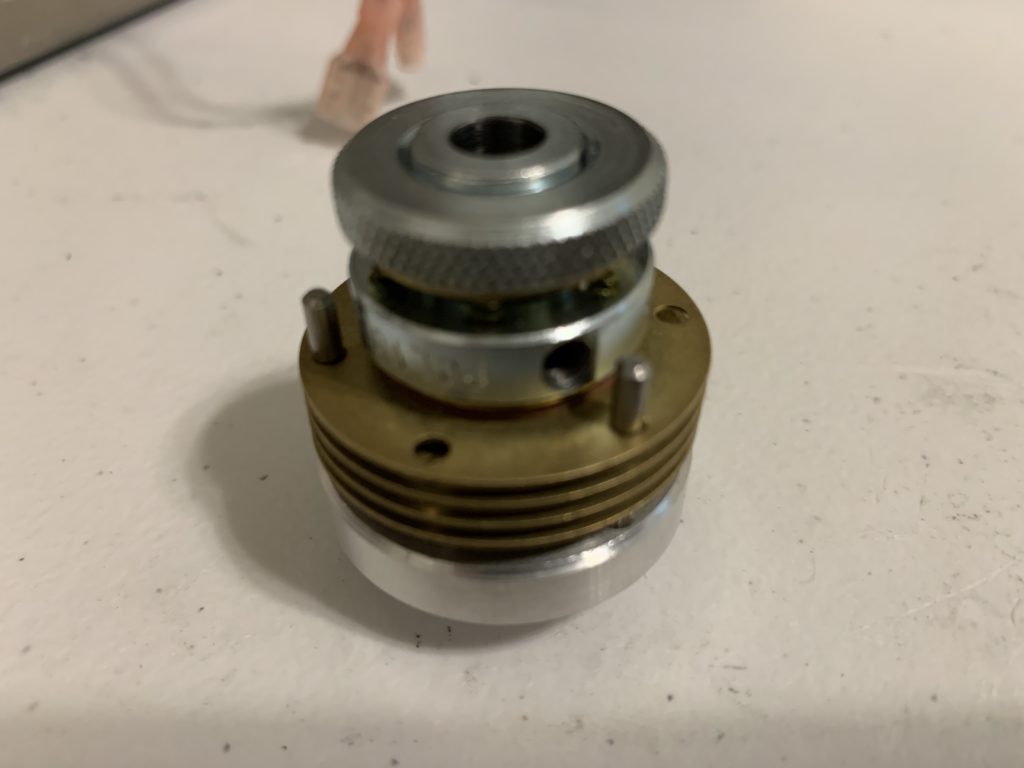
The great thing about these polyclutches is they are built to withstand long-term abuse. The knob at the end allows you to increase or decrease the amount of slip in the clutch very precisely and consistently so they were perfect for this purpose. I can easily adjust the slip until I’m happy with the feel and it will maintain that slip well beyond my needs.
The only downside is they take several weeks to get. I was told they are built to order and go through stringent testing before they are shipped which creates some delay. They’re around $110 each, so not cheap, but a lot cheaper than buying a whole new TQ! Well worth it in my opinion.
Creating the Spur Gear
Once I got the clutches in hand, the next step was to design a 3D-printable spur gear that could mate to the larger gear and also accommodate these polyclutches.
That’s when I fired up my Autodesk Fusion360. It’s free for hobbyists and a powerful design tool for making 3D models and then outputting to a 3D printer.
Now it was a matter of a LOT of trial and error (I think I went through 25 iterations before I felt it was about right).
First, there is apparently a lot to creating gears. The number of teeth, the angle of the teeth, the curvature of the peaks and valleys, the mating pressure, and so on. It’s one thing if you’re designing two matching gears from scratch…you can set the parameters for a perfect fit. But I already had a giant gear attached to the throttle levers and I had no idea what its parameters were. So all that trial and error was to ensure the spur gear I designed was exactly the right fit and size for what I needed. No small task (for me anyway!).
Second, I had the figure out how to integrate the polyclutch into the spur gear design. Again, this is where I had to do a lot of trial and error. Each time it didn’t go right I had to redesign, and then had to wait for a long 3D print process to test out the results.
The really tricky part was getting the spur gear to mate with no binding, and be in exactly the same plane as the main gear. This forced me to sink the clutch into the gear to get everything to line up correctly.
I also had to figure out how to get the gear to mate with the clutch. I used pins (actually just some brass standoffs I had lying around) pressed into the gear that also pass through the clutch plates, yet allow the clutch plates to float so the clutch plate tension could properly be adjusted with no binding.
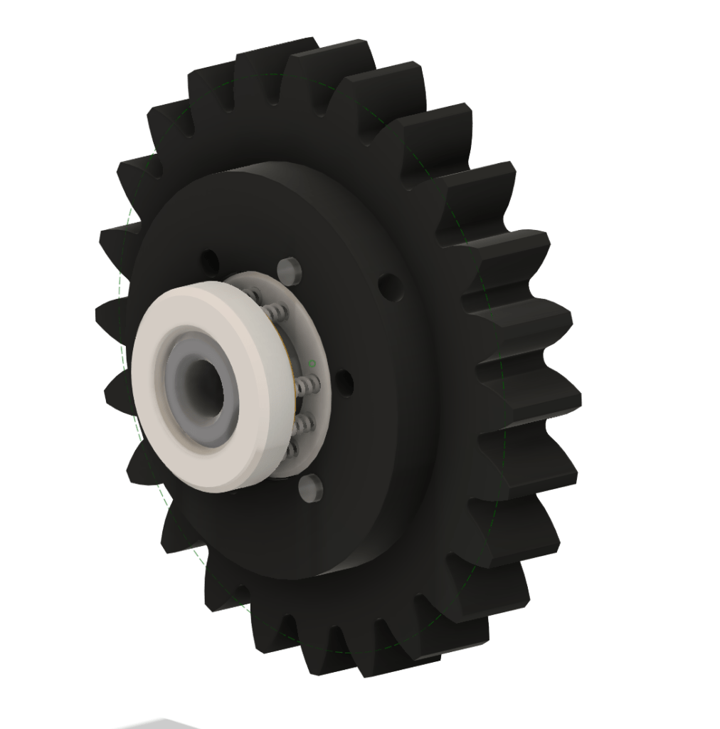
Spur gear with slip clutch added 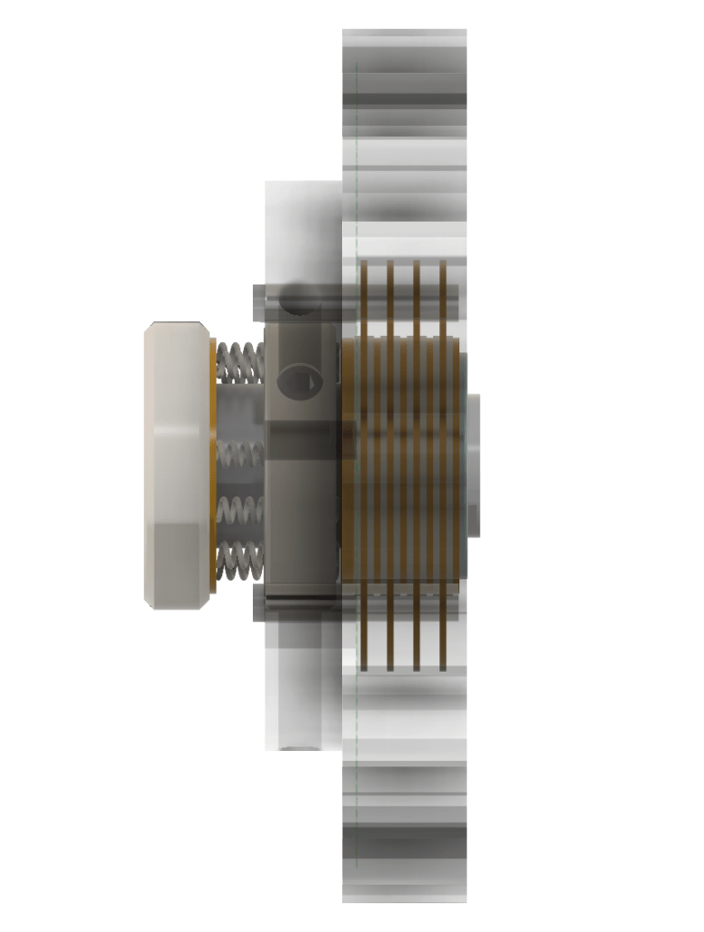
See-through side view of spur gear with slip clutch added
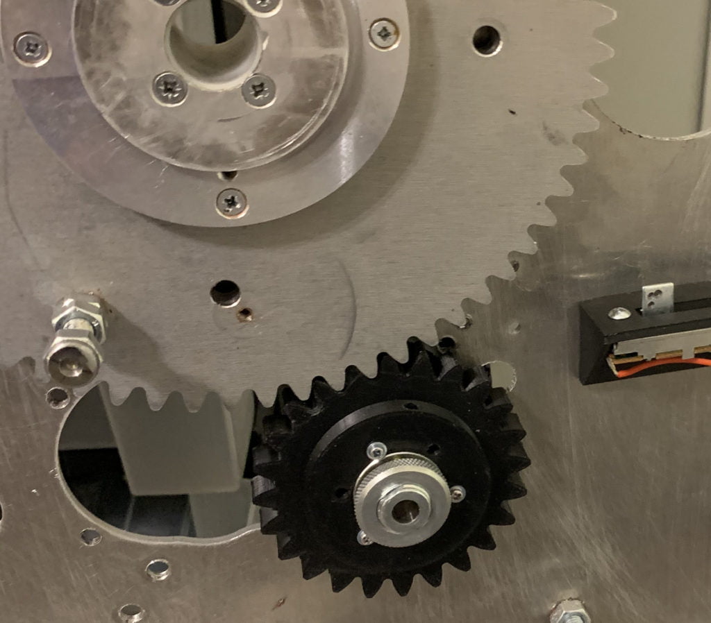
The Final Result
The end result. Exactly what I hoped for. The clutch center is affixed to the drive motor shaft with two allen screws. The clutch plates are connected to the spur gear using three pins (brass standoffs) with a washer and screw at both ends to keep the clutch in place but allow the plates to float. And the adjustment knob is easily accessible to adjust the amount of slip the gear/throttle handles have against the motor.
I’m very happy with the final results and trial testing with the sim is looking very positive so far.
Linking the Throttle Levers
Now that the TQ levers were geared and clutched much better, I needed to fix the slide potentiometer (“pot” for short) linkage to the throttle. The slide pot transfers lever position into an electronic value. That value can be output to an interface board and subsequently transmitted to the simulator as a numeric value.
The original linkage used a threaded shaft with one end screwed into the large gear using a type of ball joint, and the other end fastened to the slide pot slider arm using a metal model airplane aileron link. The pot mount was a flimsy piece of rubber sandwiched with two pieces of sheet metal and cut/scored to make a right angle. This terrible design allowed the potentiometer to move up and down easily. I’m not sure why a solid mount was not used but this obviously would not do.
The original slide potentiometer and linkage to the throttle lever
So I set out to make a replacement mount for the pot in Fusion360 that I could print on my 3D printer This was fairly easy and didn’t require a lot of iterations to get right.
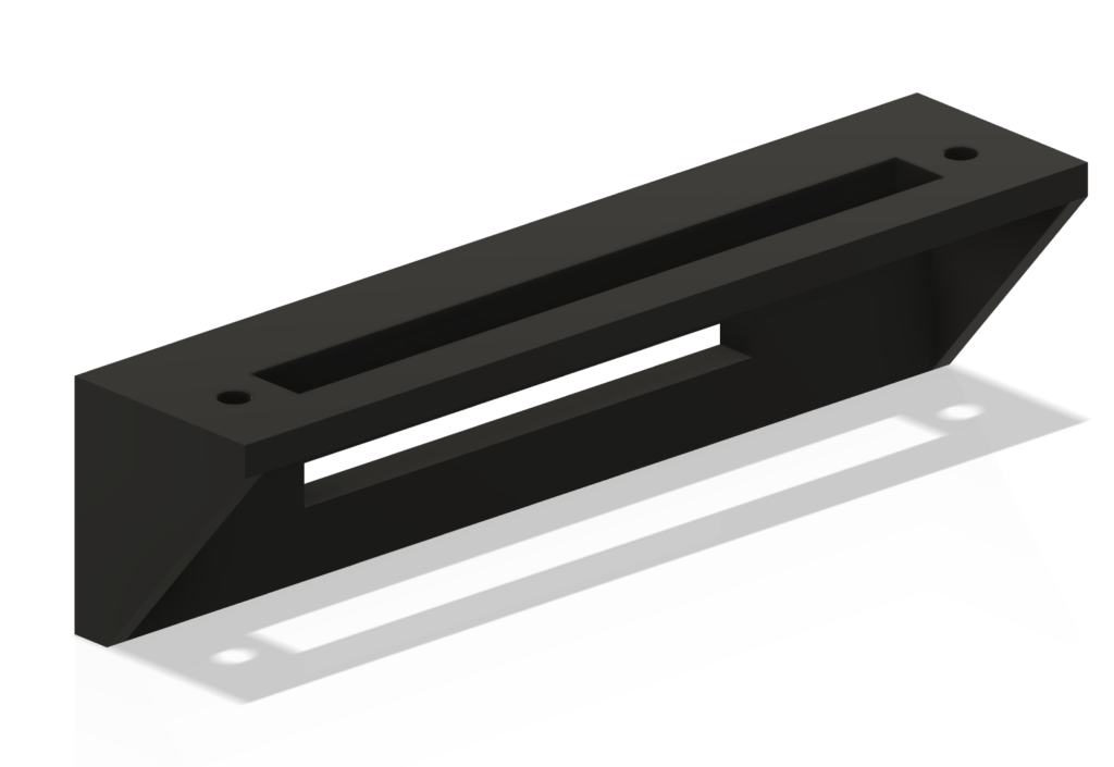
3D drawing of replacement pot mount 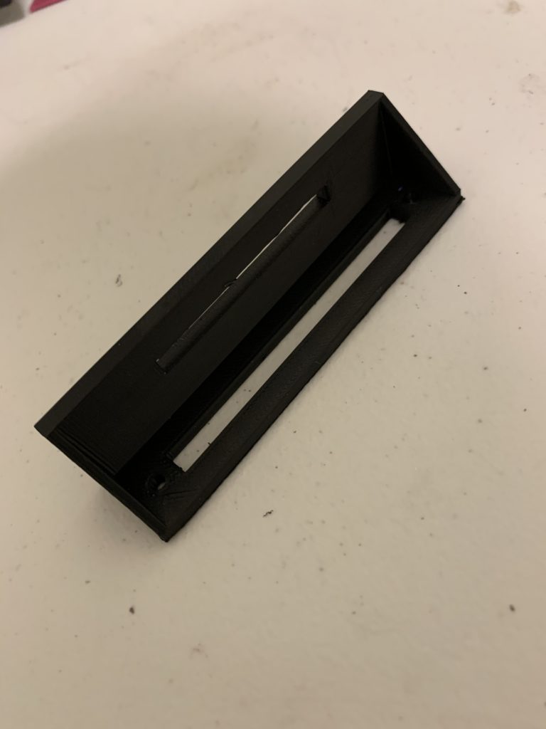
New pot mount printed with 3D printer 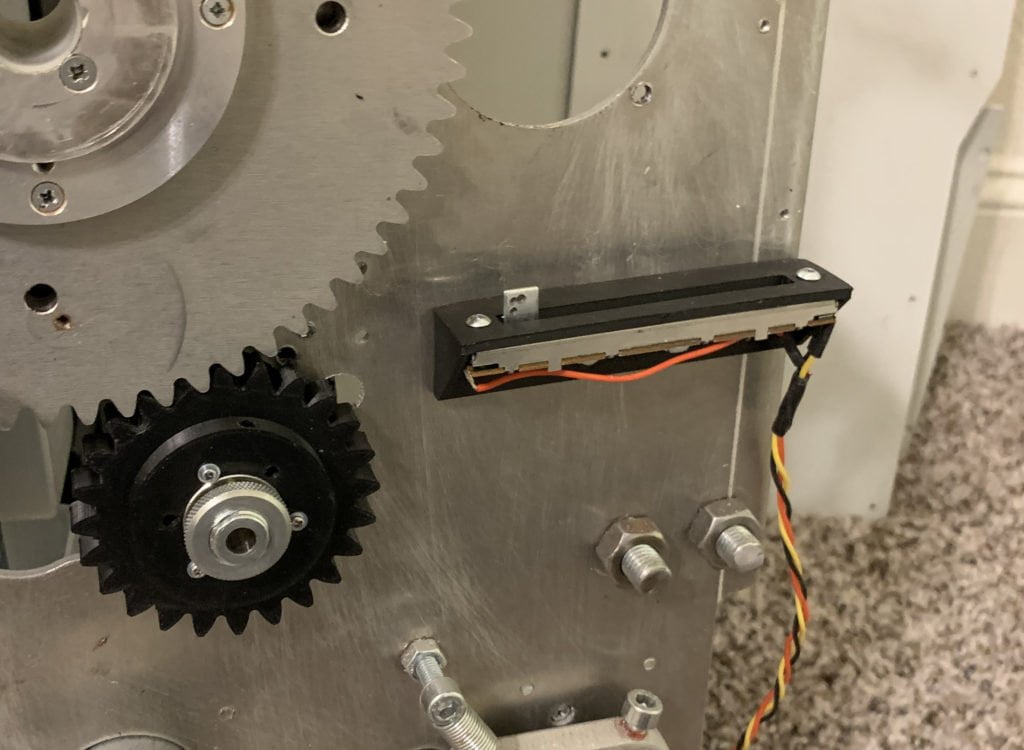
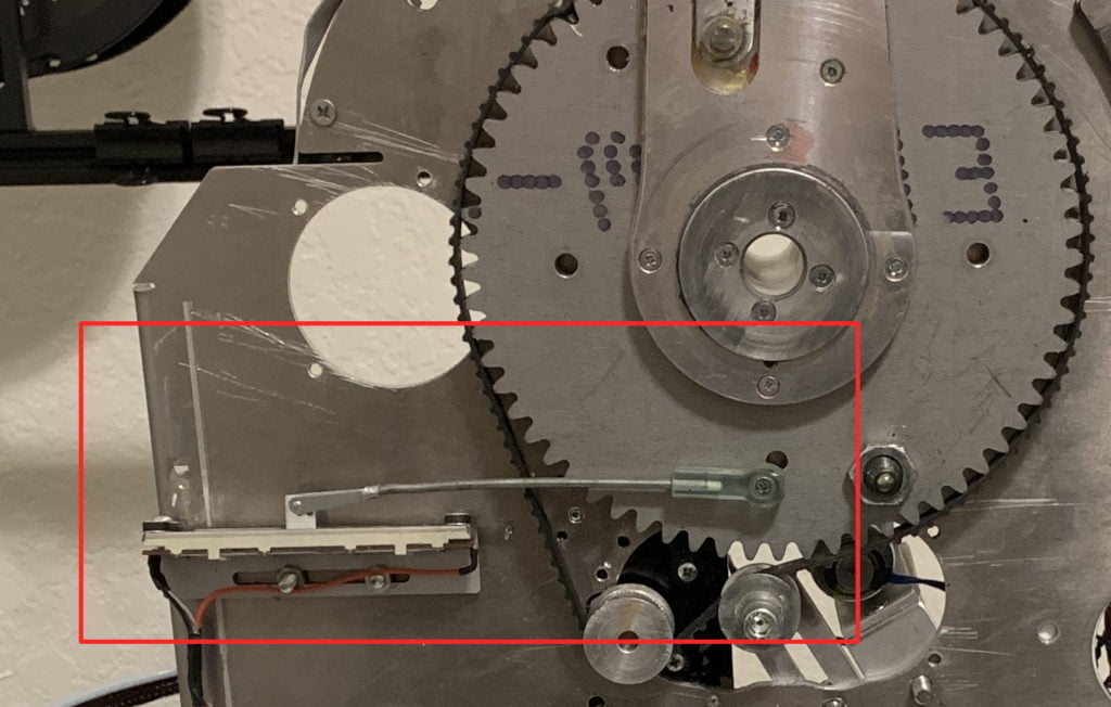
New pot mount installed
With the new mount in place, I added a better linkage between the lever and the pot, again using a threaded aileron shaft from a hobby supply store and better metal clevis pin linkage (with a piece of rubber model airplane fuel tube over it to keep it from opening) and new model airplane ball-end. The intent here is not to have to ever open this up again so I better do it right the first time. It’s just too much work to take apart!
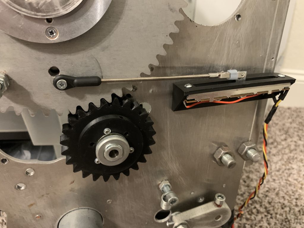
New ball end, threaded shaft, and metal clevis with rubber fuel tube to prevent the clevis from opening and coming loose
Interfacing
Now that the mechanical side is done, I have to make this work with the simulator. Since I ripped out all the original electronics which were dated and no longer supported, I’m starting from scratch with all new electronics.
For the throttle levers, I needed a servo motor controller card that 1) would interface with my ProSim avionics software without any additional external software and 2) would work with the existing Modelcraft DC motors. After a bit of research on various flight sim forums, I settled on the Polulu JRK 21v3 cards (version 1, not 2 which is not supported by Prosim yet). They’re tiny, fairly inexpensive, and work with my motors and have native drivers in Prosim.
You can see a vertical column of four small JRK cards on the left of the picture below.
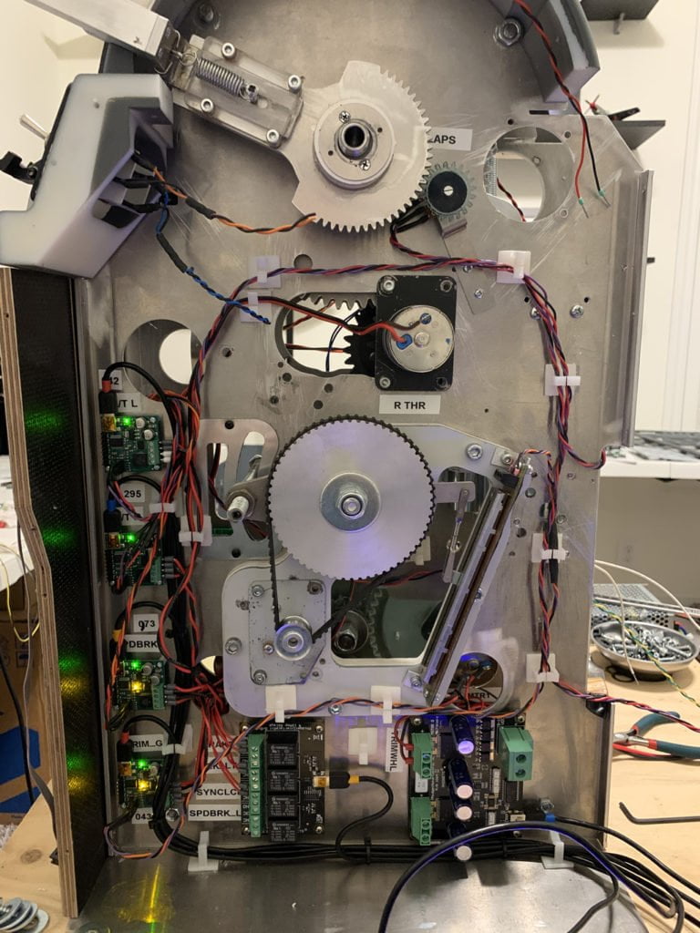
Each throttle lever requires one JRK card. The JRK’s take feedback from the slide potentiometers connected to the throttles and translates it to a motor output back to the throttles. Thus, the auto throttle positions can be known by Prosim and also controlled by Prosim.
Within Prosim, you indicate which card you want controlling each throttle along with its associated feedback potentiometer, and then calibrate the throttles within Prosim by moving the Prosim slider, which in turn moves the throttle levers, and set the min/max points.
Conclusion
The rebuild of the RevSim TQ auto-throttles with new clutches, custom made gearing, and electronic interface cards was a fairly difficult challenge that took a lot of time to research and build, but the results turned out very good. These changes allowed me to extend the life of my fully-automated throttle and save me a significant amount of money not having to buy a replacement TQ.


2 comments
Hi Tony
Nice use of dynatec clutch…..
Glad it worked for you 🙂
WilloW
Have the same Rev Sim TQ and it is a hassle with the SIOC scripts, not 100% happy… But my focus now is getting pedals as my cheap-as-dirt pedals finally stopped working. Someday… I’ll need to address issues with the TQ and this article made me wonder if I could change IO cards and get simpler interface to ProSim… Thanks