
Last Updated on April 6, 2021
I have to say, I’m really enjoying my 3D printer. For less than $300 for a Creality Ender 3 printer, coupled with Autodesk Fusion360, I’m able to make just about any component I need on a small scale. Comes in really handy when you’re willing to put in a little extra money and time to save a few dollars out of pocket. It’s also nice because I can put more detail and make my parts more realistic than many of the off-the-shelf components.
Wet Compass
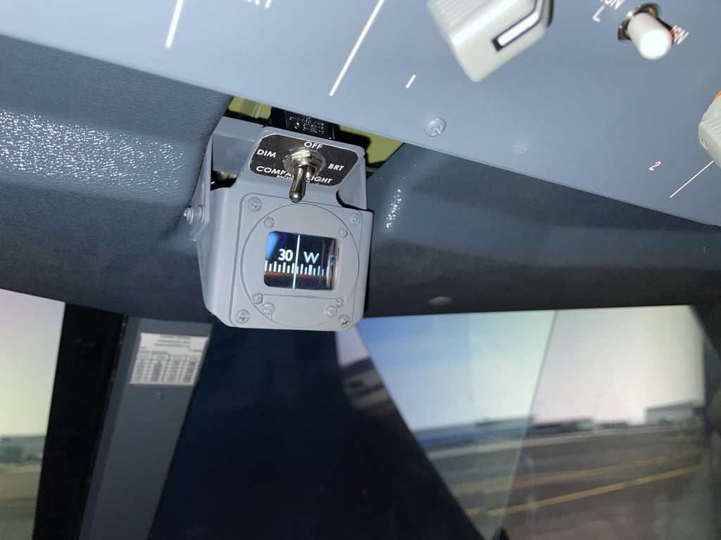
I just finished designing a replica working Boeing 737 wet compass to add that nice “finished” touch above the instrument panel. Note the compass deviation card on the window post behind it Just a simple 3D-printed holder and a laminated card. Together, it all adds just another level of immersion.
Creating the Compass
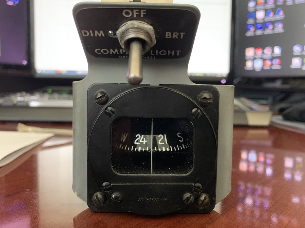
In order to create a fairly accurate wet compass, I borrowed a real Airpath wet compass from a friend of mine. These are used in older 737’s but it’s close enough. There are a number of variations of wet compasses used in these aircraft. The newer 737’s have a round bezel that curves inward with an adjustment knob on the front as seen in this photo.
Using a Micrometer I measured all dimensions and translated them to a Fusion 360 model. It takes time and patience but once you get the hang of it, it’s not too hard.
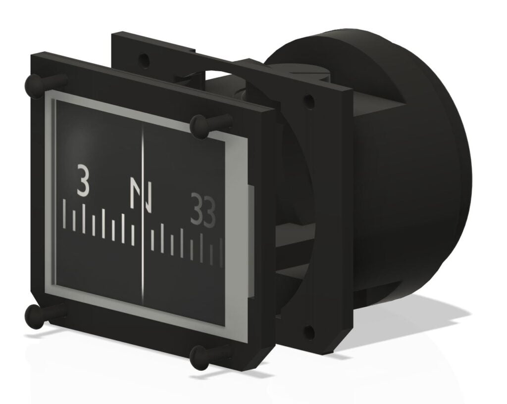
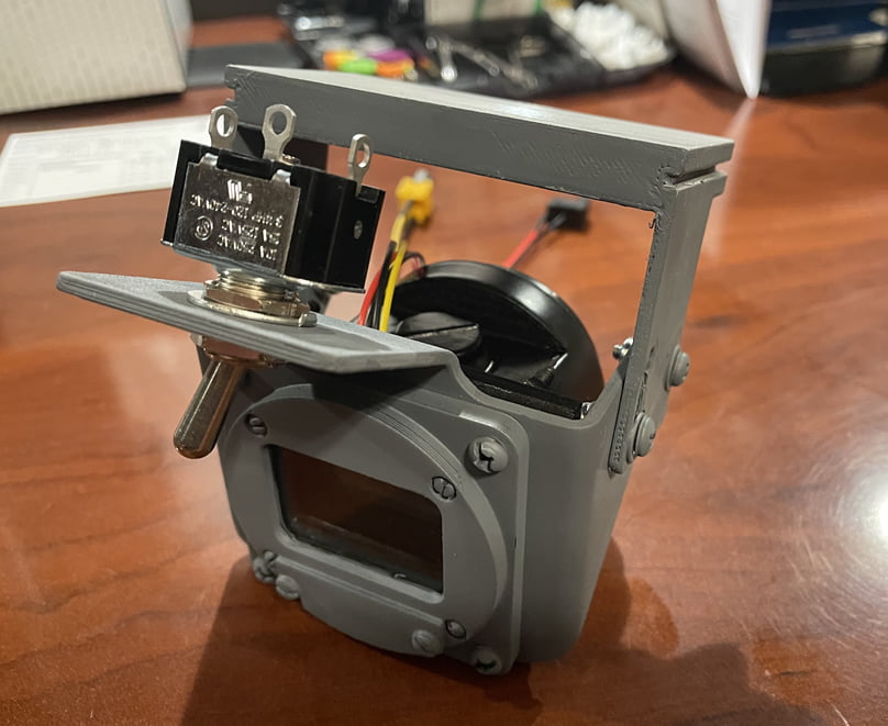
You’ll notice I used a LCD screen rather than an internal rotating mechanism. I did this because it’s simpler…no motor, gears, lighting, driver board, or custom programming. The Prosim avionics software already has a functional Wet Compass display output which makes it easy to throw the image on a LCD.
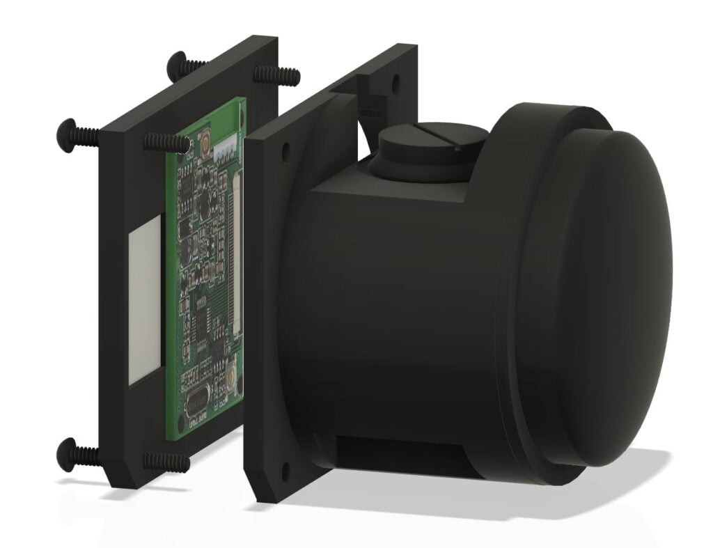
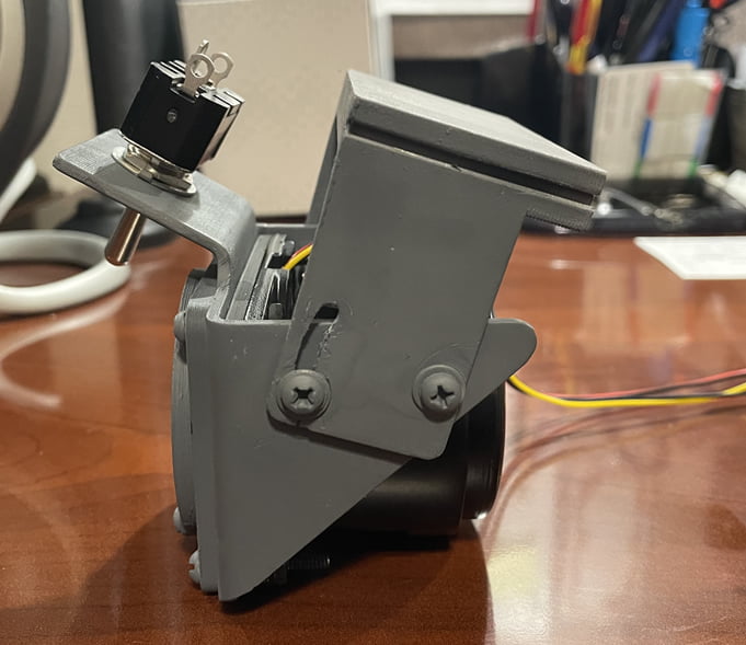
The challenge, though, was finding a color LCD screen small enough and bright/clear enough to use. I settled on a 2.5″ LCD and driver from Adafruit (https://www.adafruit.com/product/912) which was about as good as i could find at the time, then designed the frame around it to support the LCD and associated driver board mounted behind the LCD and within the barrel of the compass to keep things nice and concealed.
I then purchased a MINI HDMI to RCA signal converter (just search Google for AV2HDMI) to connect my computer’s HDMI display output to the RCA jack on the LCD.
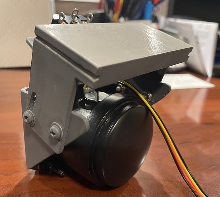
The only downside is the LCD is set back a bit since it’s not small enough to fit within the bezel, but in the end it still looks pretty good.
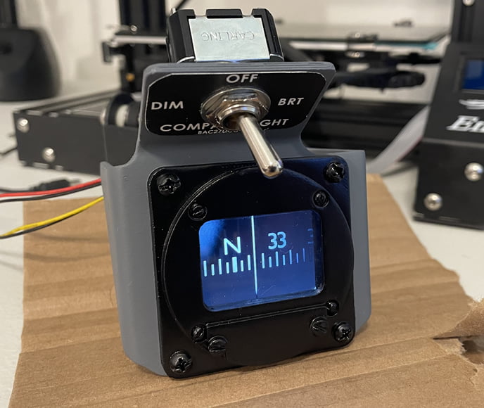
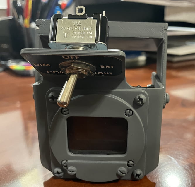
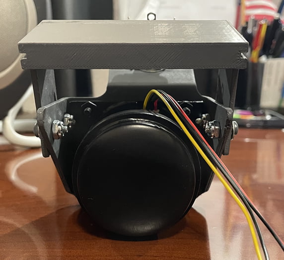
Final Product
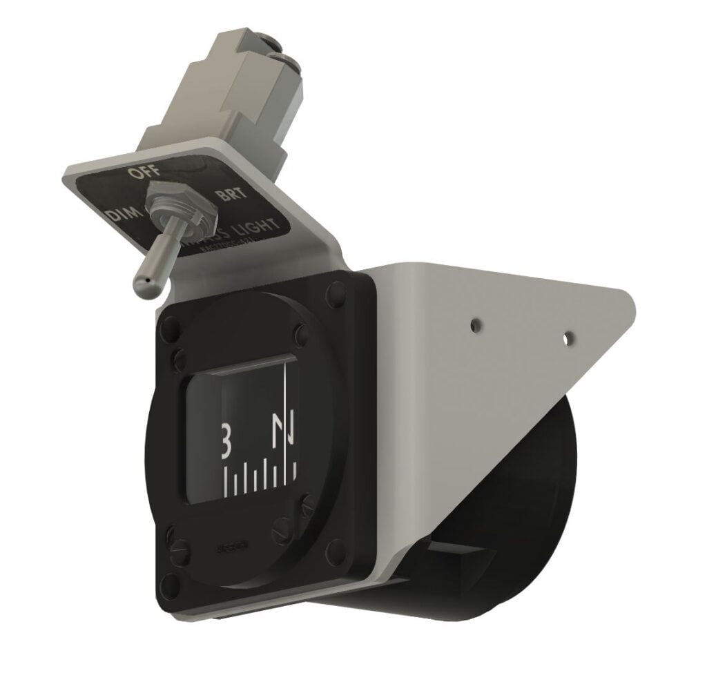
Here’s what the final product ended up looking like. I later realized the NG’s have a gray bezel, not a black one, so you’ll also see the updated re-painted version below. I also designed a 3D-printed mount with slots/channels near the top to allow the entire thing to slide into the gap in the Flightdeck Solutions frame without the need for bolts or screws. Easy to remove later if needed but nice and solidly mounted otherwise.
Miscellaneous Parts
I’m in the process of adding some other 3D-printed parts to finish out the sidewalls a bit more. A cup holder, map holder, and some window handles as you can see. After a lot of coats of primer and some airbrushing these are going to look great!
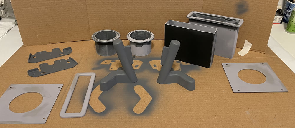
I can’t take credit for these models as I got them for free from Thingverse. They’re made by the talented Mr. Karl Clarke from 737DIYSIM, so props to him for making us a bunch of cool (and free) models to use!
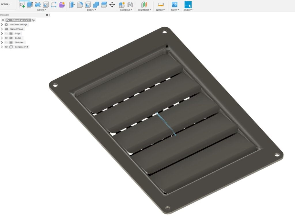
I am, however, working on a sidewall vent that is a bit more accurate than any I have seen so far. Stay tuned for more!
Last Words
So, is any of it absolutely perfect and 100% accurate? No, of course not. Home sims often have to compromise a bit, usually due to lack of good real-world reference material and measurements, material costs, parts availability, and skills of the builder. So we approximate as best we can.
My end goal has always to be to get things as close as I can, within reason (and for everyone it’s different) so that I can sit in the cockpit and it looks and feels about right. And that’s not a bad thing.


4 comments
Skip to comment form
Hi Tony,
I was just looking at the mount you made to fit the FDS shell. Such a great idea and I never thought of it myself. I was wondering if it would be possible to get the stl you designed for just the mount part. It would save me several hours (or 10) haha, of printing and trial and error making one myself. I’m printing out the Josh Katz version but I plan on using a small stepper to drive the cylinder. I use CURA for all my printing and Tinkercad to design. Retired and on a budget lol.
With Kind Regards,
Ed Burton
Author
Hi Ed, sometimes simple wins the day! This worked out perfectly. Look for an email from me in the near future with the CAD file. Cheers!
Can you post the arduino code you used to make the compass spin and connect to the computer?
Author
Hi, there is no Arduino code because there are no moving parts. My compass uses a mini LCD to display the ProSim compass from the ProSim Display module 🙂