
I discuss in detail how I built my first Boeing 737 overhead from scratch, and give you some things to think about when you decide to build yours. The end result was fantastic but the learning curve was steep and there were a lot of lessons that came out of it that I was able to apply to my second generation build.
How I built my first overhead
I was excited to start building an overhead for my flight simulator. It really adds to the sense of immersion and it’s just such a cool factor that takes your simulator to the next level.
knew I needed to start with a frame. But how big should it be? What should it be made of? What switches did I need? How should I wire it? How do I light it? I had lots of questions and no instruction manual to follow.
Here’s how I fumbled my way through it.
Requirements
I decided I wanted a swing down panel like the real aircraft. This would help me do maintenance without removing the entire overhead. I settled on building an enclosed box that would allow me to easily manage the overhead as a single, self-contained unit. I also wanted an accurate looking and operating overhead.
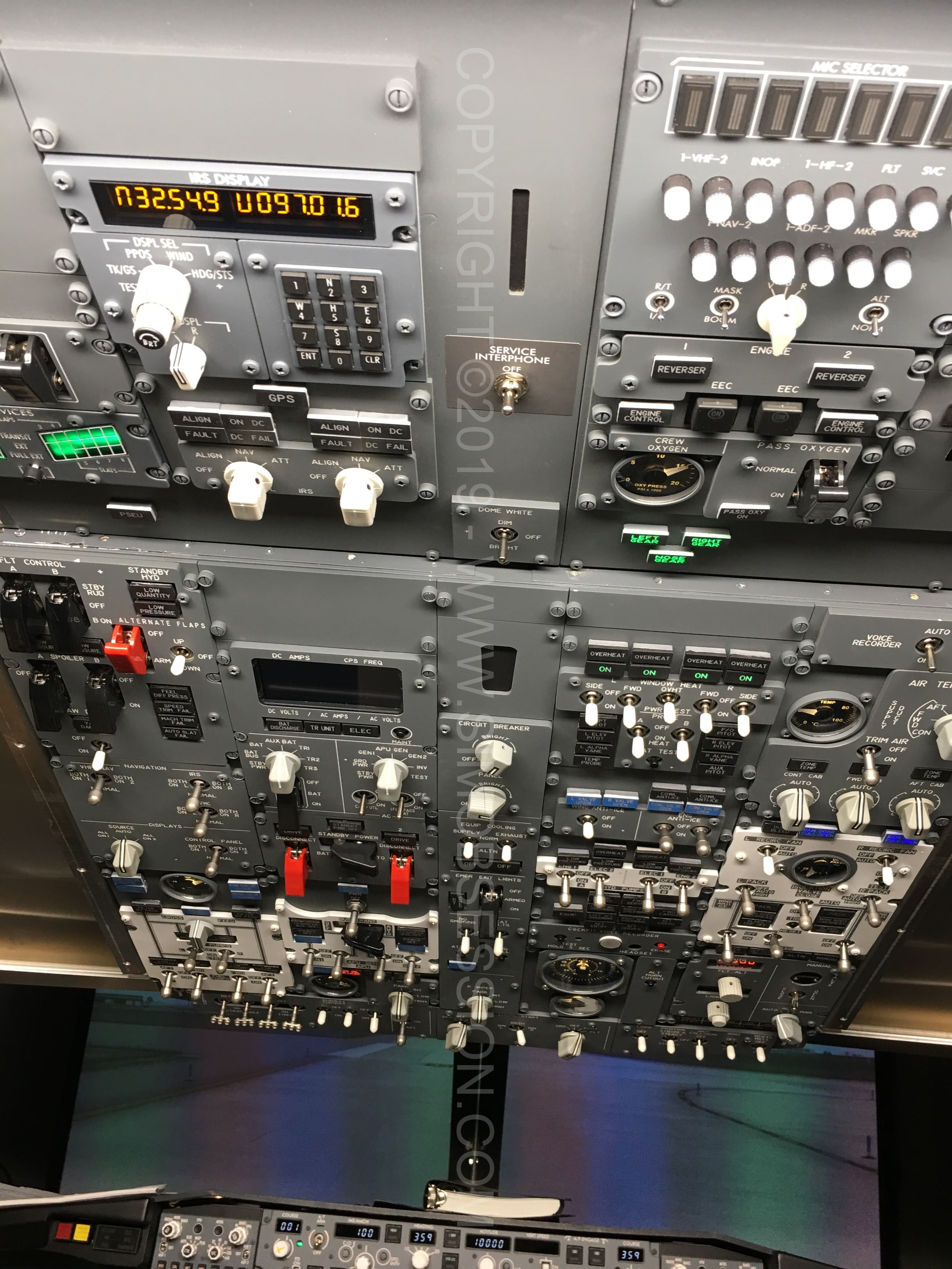
After some research, I sourced reasonably priced panels and hardware from CockpitSimPartsin the UK. It took a little while to get them as they’re manufactured to order. However, they are good quality and quite accurate for the price. Overall, I was happy with them and as you can see, they look very good.
The downside is they are thinner than real panels at 5mm versus 6mm. If you’re mixing and matching different panels from different places, that could make things look a little odd. These panels also have an acrylic plastic back panel plate versus metal. This proves to be somewhat of an issue when mounting switches. The plastic can easily crack or flex under repeated use. This is a problem when you’re using real aircraft locking toggles that require some effort to unlock the switches. If there’s an option to order metal back plates, I highly recommend it.
The other issue I found out later is that these panels are back-lit. You need to shine light on the backs of the panels to light the front markings. This differs from panels like FlightDeck Solutions IBL or real where the bulbs are built into the panels. This proved to be a difficult problem to solve but not impossible.
Sizing the Frame
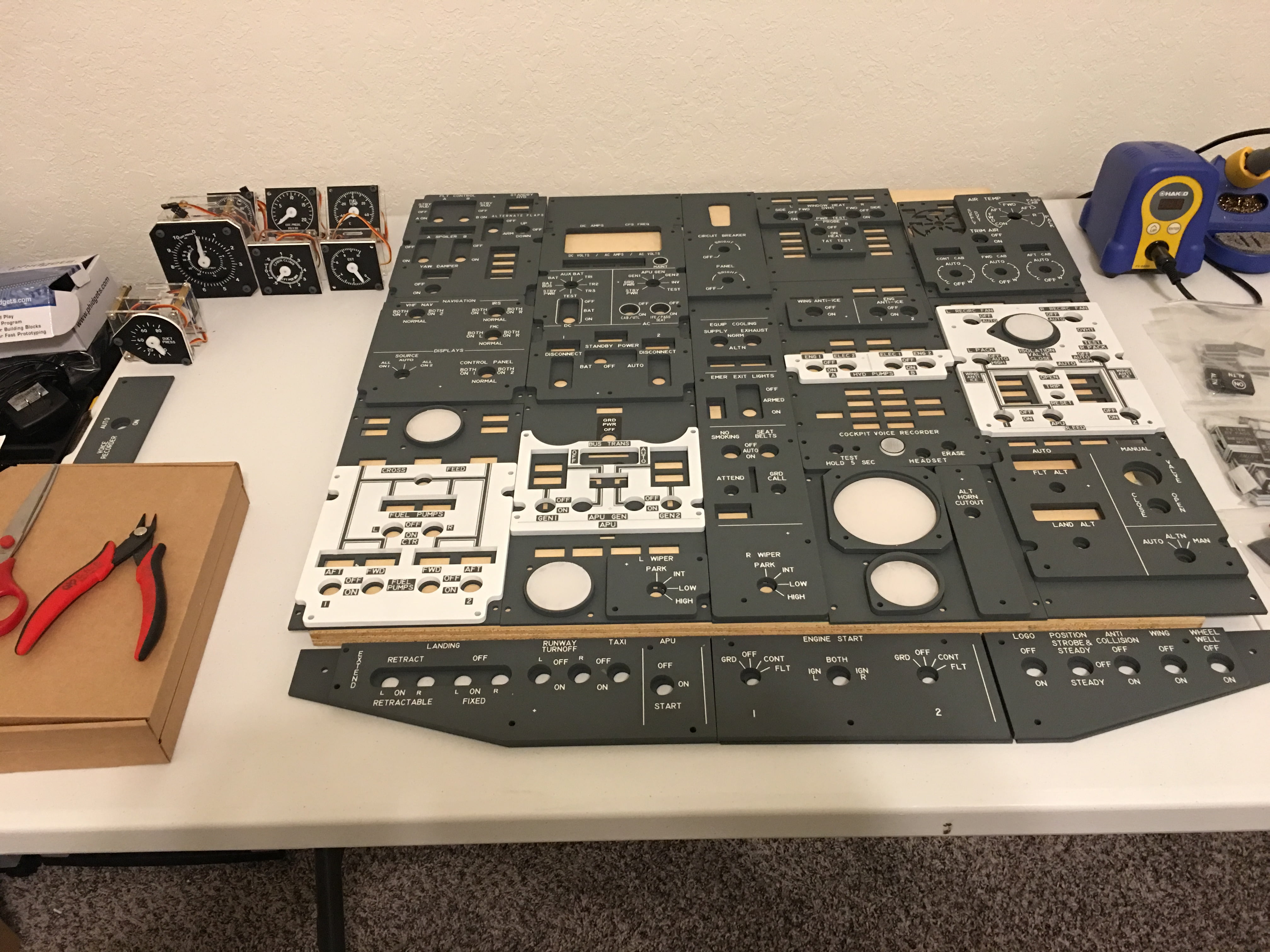
To determine the dimensions of the frame I laid out the panels on cardboard and arranged them appropriately. I then traced around the perimeter with a pencil. This gave me the outer frame dimensions and the location of all the screw holes the panels would mount to.
Swing-Down Frame
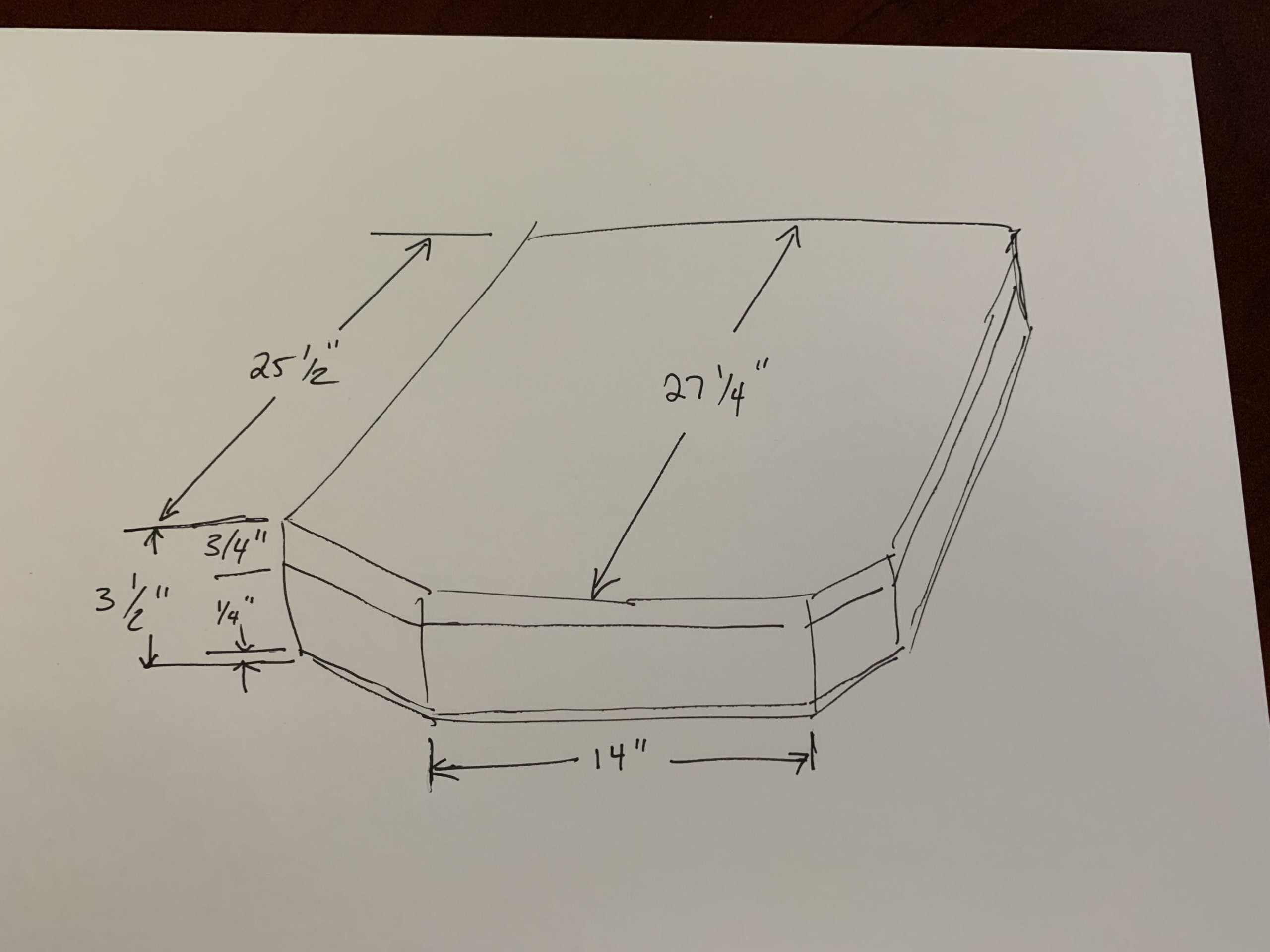
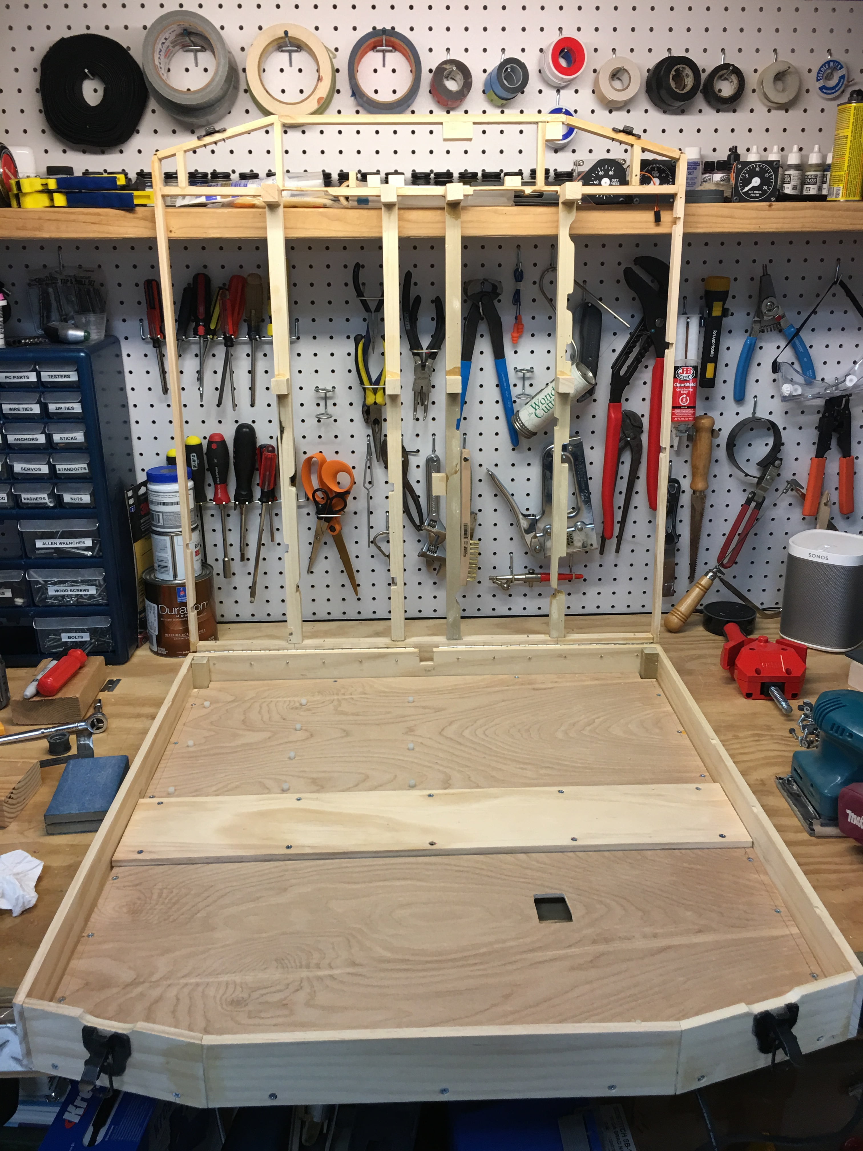
First I framed out the swing-down top using the drawing I had made earlier as a guide. I laid out a wood frame using 3/8″x3/4″ wood strips that would be reasonably strong, but not interfere with mounting the panels. I test-fitted the panels until everything lined up right and adjusted as necessary for clearance.
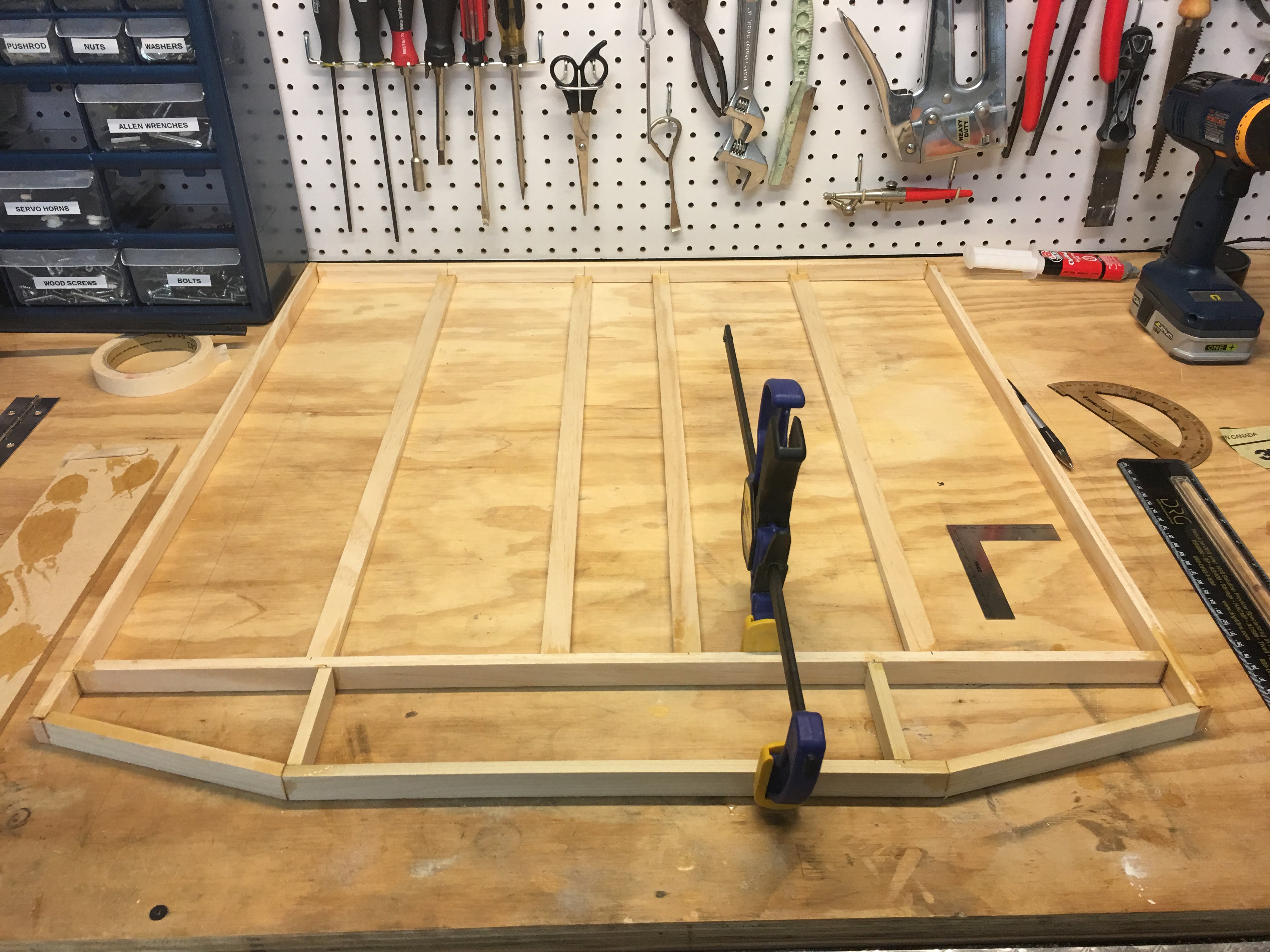
NOTE: I later determined the main ribs from front to backshould have been thicker. These ended up slightly sagging due to the heavy weight of all the components.If done again, I would use aluminum for a much better strength to weight ratio. It would also allow forthinner frame walls reducing clearance issues. Something to think about for your build.
Frame Box
Next, I started the lower portion of the frame box. I estimated the box height from the available space in my FlightDeck Solutions shell. This was approximately 3.5″. The frame was made with 1/4″ x ~3″ wood strips.
I added a raised “hump” in the middle of the box to accommodate the cross-brace in the FDS cockpit shell. While the shell’s cross brace didn’t seem necessary I chose to leave it for strength. Unfortunately this reduced internal space in the center a bit but it wasn’t a major problem.
I used piano hinges at the rear of the box to allow the top panel to swing down, then added latches at the front to keep the box locked shut. This allowed me to easily unlatch and swing down when needed.
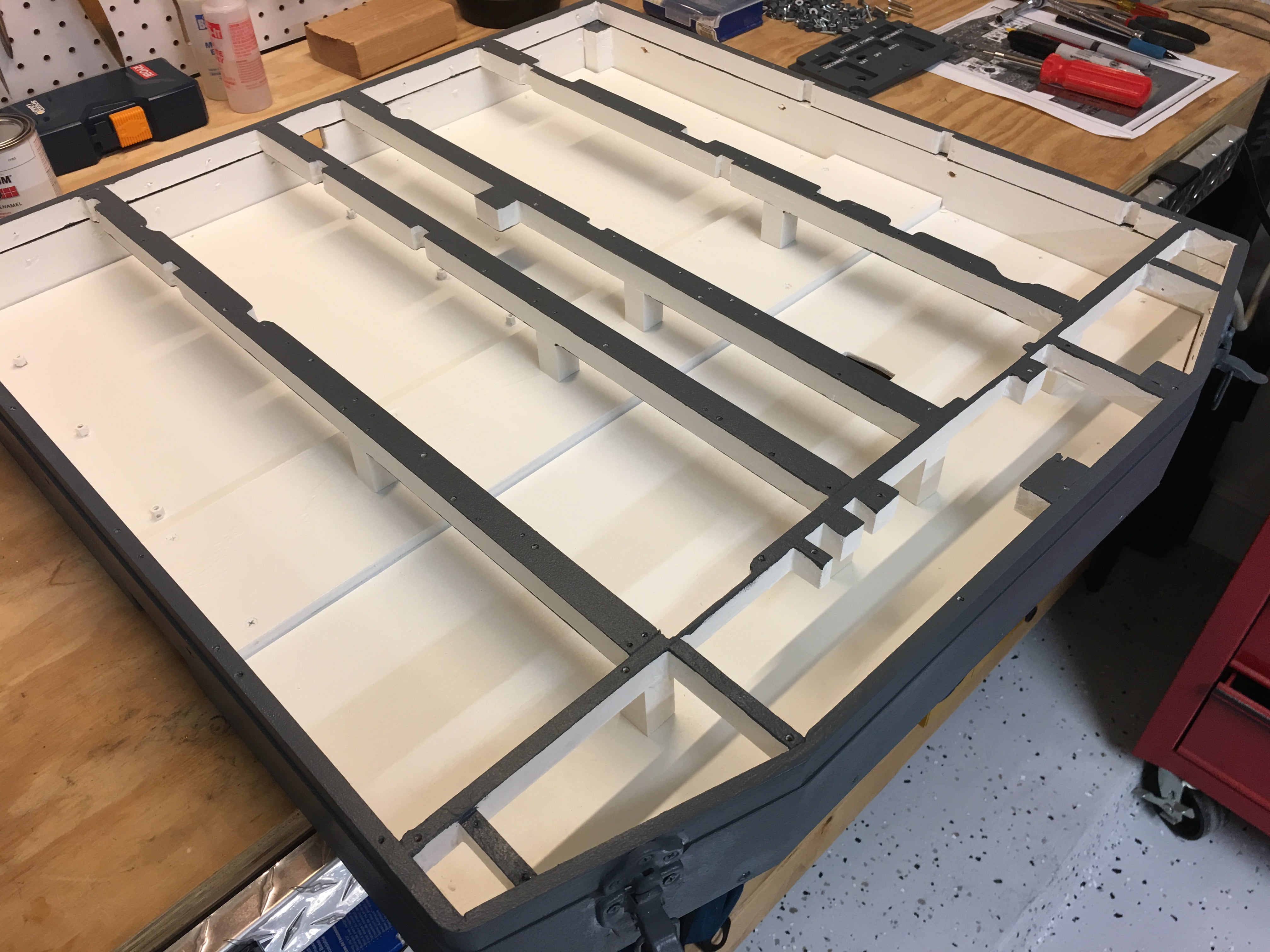
I then checked fit by loosely placing the box in its final mounting location. I was able to determine the proper mounting position, mounting hole locations, and general fit. Then, I adjusted as needed.
Lastly, I painted the outside frame with Iron Grey latex paint and the interior with white latex paint. The white helped (in theory) to reflect light inside for improved back-lighting.
Preparing to Wire the Panels
Wiring the panels is probably the most challenging and tedious part of the whole project.
Here are some thoughts on wire.
- Use 22 or 24 Gauge wire for all your internal wiring
- Use 16 Gauge wire main power wire
- Color-code to make identification easy. You can, of course, use any colors you want. This is just what I chose:
- Yellow – 12V power
- Red – 5V power
- Black – Ground
- White – Switches
- Purple – Potentiometers.
- Red – LEDS (since they generally also run off 5V).
Here are the interface boards I used to connect the components:
- FlightDeck Solutions SYS4X – My primary switch and LED controller. Components are connected in groups of 8 with one common ground. Pretty straightforward and uses less Black ground wire. Dual brightness LEDS are a little extra effort but is possible. I chose the Phidgets LED card for dual brightness LEDs.
- Phidgets LED card – I used this card for all my blue, dual brightness LEDs. This is not necessary if you use a PCB with dual inputs and a resistor..one input is for normal brightness; the other input runs through the resistor for dim brightness.
- Phidgets Relay card – Used to operate the magnetic start switches I bought from Anders Sim Parts.
- PoKeys 57E – Ethernet card that handles 7 Segment displays as well as switches and LEDs. Very versatile.
- Small LCD screen and video board – Used for the ELEC panel LCD display. I did this is a little different than most do. Instead of a 7-segment display, I wanted the correct dot-matrix style numbers per the real aircraft. I used a TFT LCD instead and I display the Prosim ELEC panel on it.
NOTE: The FDS SYS4X doesn't have enough inputs/outputs to cover a fully connected overhead. This is why I also added a PoKeys 57E andPhidgets card to provide the extra I/O I needed.
Creating the LED Printed Circuit Boards (PCBs)
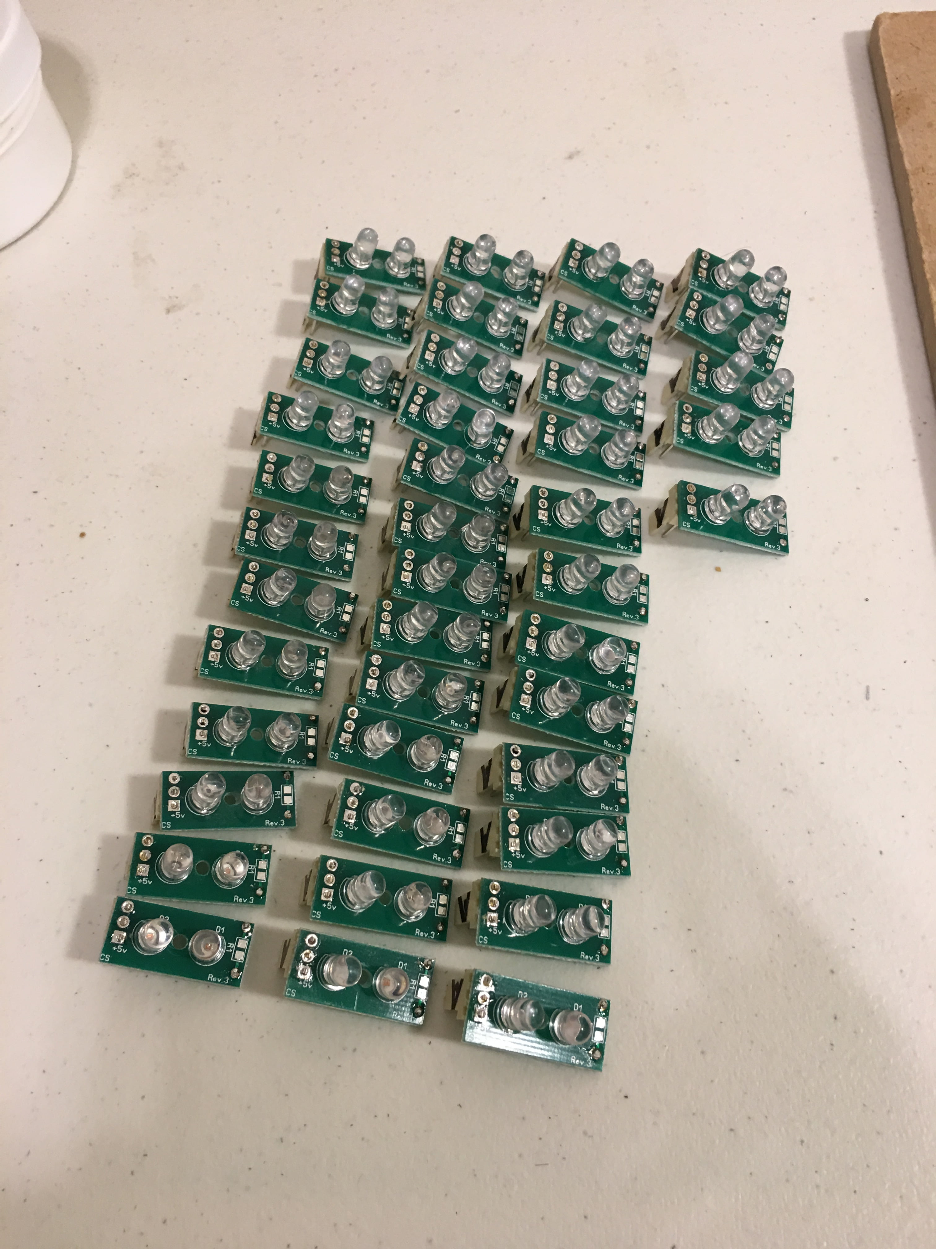
My first task before building and wiring the overhead panels was to assemble the many LED indicators I needed for the overhead. On the Forward overhead alone there are approximate 96 indicators.
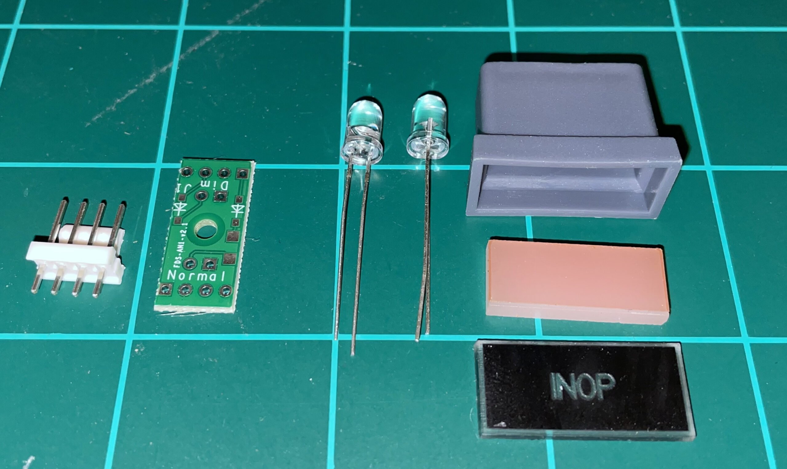
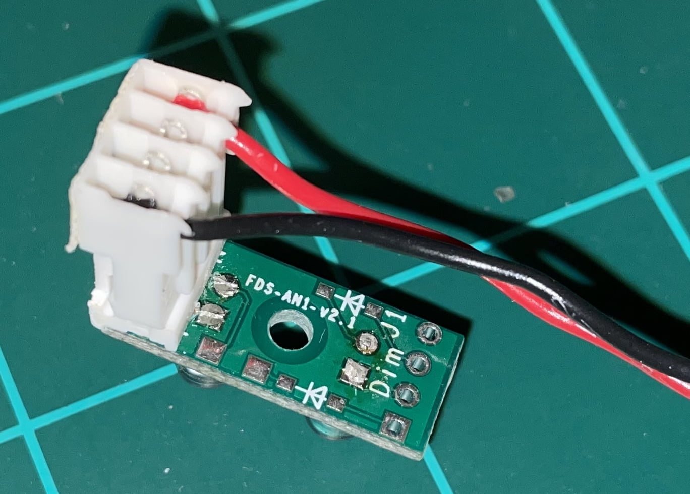
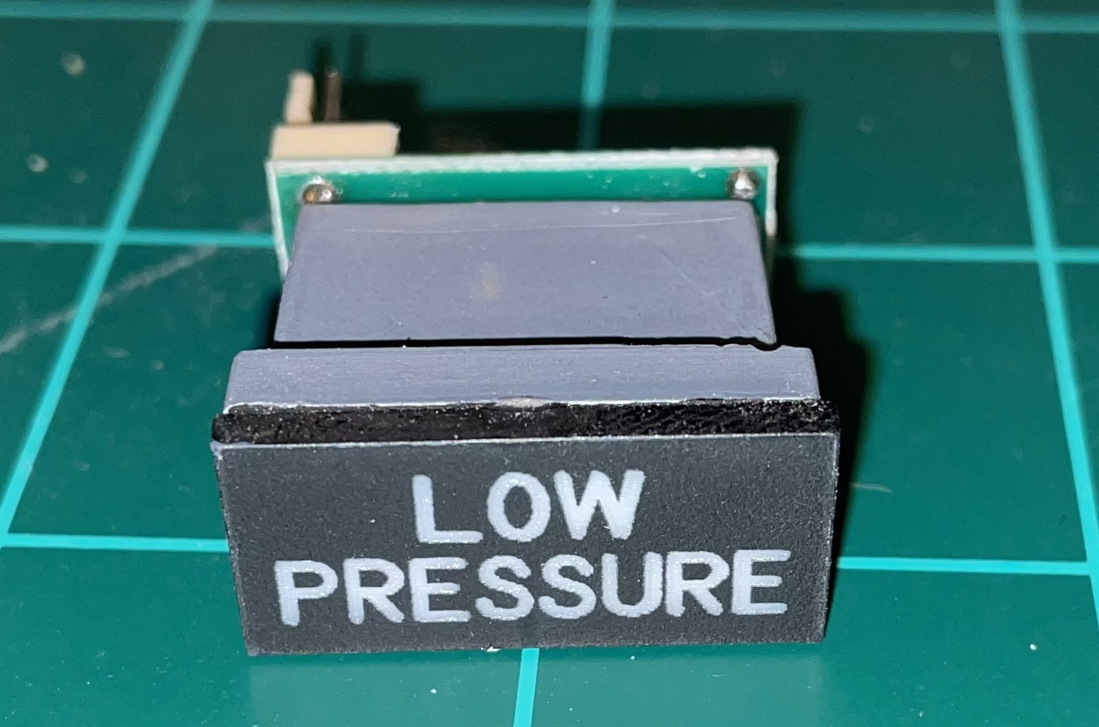
A typical replica indicator consists of two LEDs of the same color (Red, Amber, Green, Blue or White), a Printed Circuit Board, header pins, an indicator housing, usually a light diffuser, and an engraved indicator lens (see image below).
The LEDs and header pins need to be manually soldered to each board which is quite tedious and time-consuming (but oddly relaxing). Once the board is complete it screws into the back of the indicator housing with a single screw. Then, a diffuser is inserted into the face of the indicator to help more evenly spread the light. Finally, an engraved “lens” is glued or taped to the indicator housing. The complete indicator is then usually press-fit into an opening in a panel.
Note:  Many LED PCBs allow you to add a resistor to the board.  This allows you to make the PCB dual circuit capable of dual brightness.  Instead of only one positive input to the board (as seen below with the one red wire), there would be two.  One input would be a normal
circuit where the bulbs get full power and thus normal brightness.  The second input would pass through the resistor circuit and lower the voltage to the bulbs thereby dimming them. The 737 overhead has a number of dual brightness indicators this would be ideal for.
Connecting the LED Indicators
Now that the indicators are assembled, I can start wiring them into the overhead.
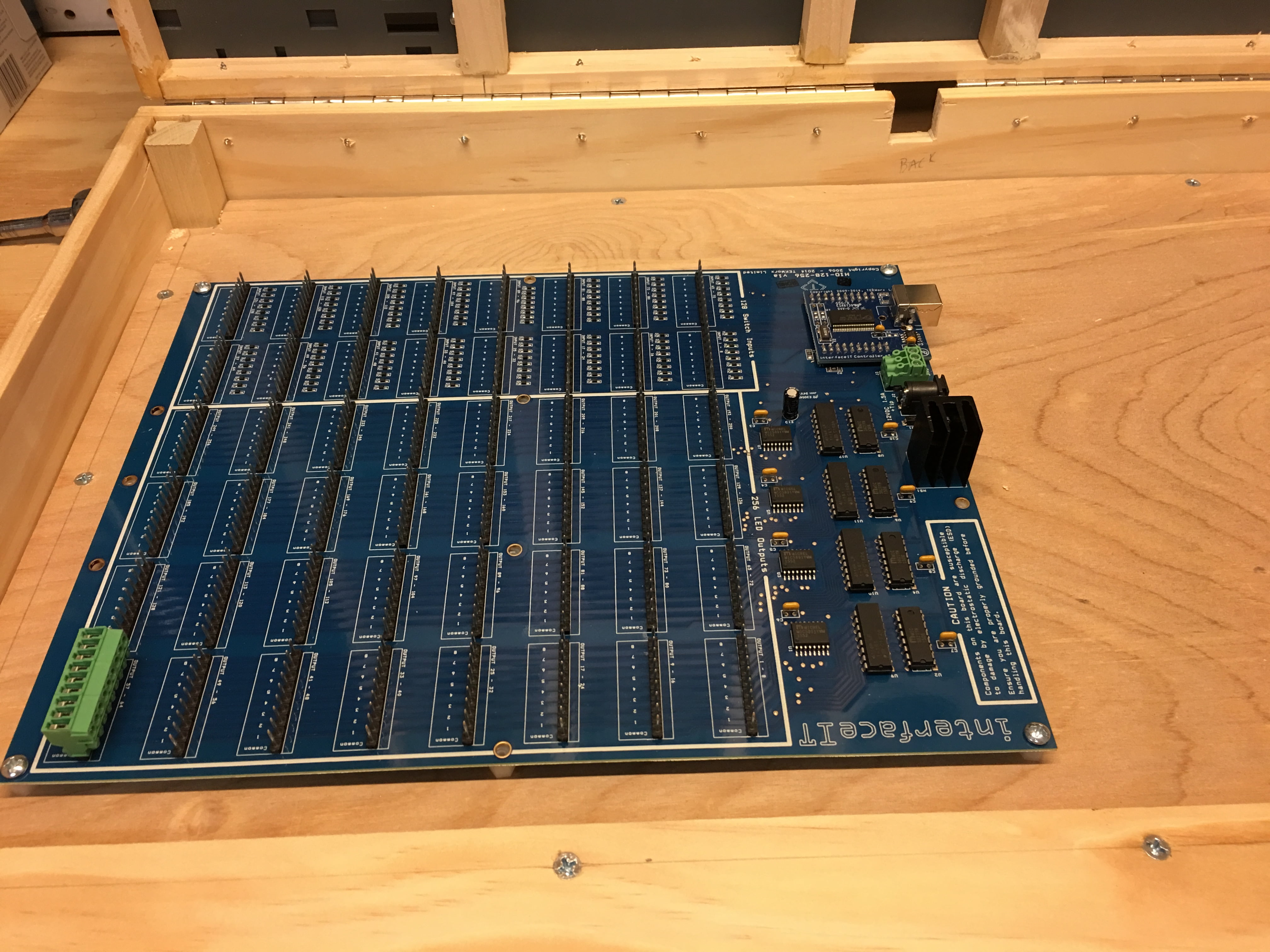
The FlightDeck Solutions SYS board is the central board in my overhead used for all of the LEDs, all the toggle switches, and most of the rotary switches.
FDS SYS board headers are arranged in groups of 9-pins (see FDS SYS4X board picture above). The first pin in each header group (pin 1) is the common ground (negative) for the other pins in the group. Pins 2-8 are the output pins (positive).
Starting with the first 9-pin header, I ran the positive lead (red wire) of the first LED Printed Circuit Board (PCB) to Pin 2 on one of the FDS connectors. I then connected the positive lead of the next LED PCB to Pin 3 on the same FDS connector. And so on until pins 2-8 have been connected. Lastly, I connected the black wires from each PCB together to the 1st header pin on the FDS board. See the wiring diagram below.
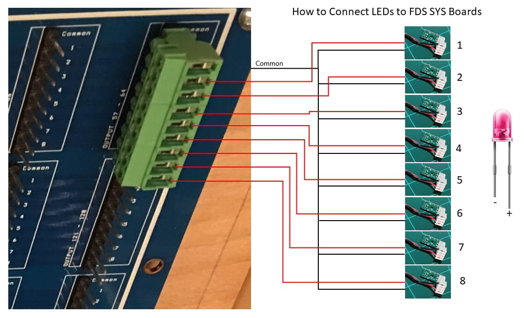
Since there are 8 outputs per group, you’ll be connecting 8 LED PCBs to each header. It doesn’t matter how you choose to group your LEDs. I chose keep LED groups close together. That helps keep the wiring a little neater and the daisy chained ground wire from having to go too far.
I continued to repeat this grouping of LEDs until all the LEDs were wired.
Once finished, you can use Prosim’s configuration menu to find a specific LED and assign it appropriately. It’s quick and easy.
Toggle Switches
The same principal applies to toggle switches. I ran 8 white wires from each input group to a terminal on each switch. I then daisy-chained a ground to the ground pin on the switches.
Three way switches are just as easy. You just run two wires from a group to two terminals on the switch, and the ground wire to the third terminal. Each position on the switch will then read as an on/off in Prosim. You can then assign the switch to any function within Prosim.
After you connect each group you should verify the switches are being recognized properly in Prosim. Like the LEDs, Prosim has a quick way to identify a switch or rotary. In Prosim’s configuration, when you move a switch, you should see it immediately identified by Prosim. If not, then you have a wiring problem that should be fixed before moving on.
Rotary Switches
Rotary switches are a bit more challenging. They are wired and behave similarly to three-way toggle switches, but their wiring is a bit more complex. You would connect each pin from a group to an applicable pin on the rotary switch. Which pins you should use and how they are identified in Prosim is a bit of trial and error. Sometimes can be a bit frustrating.
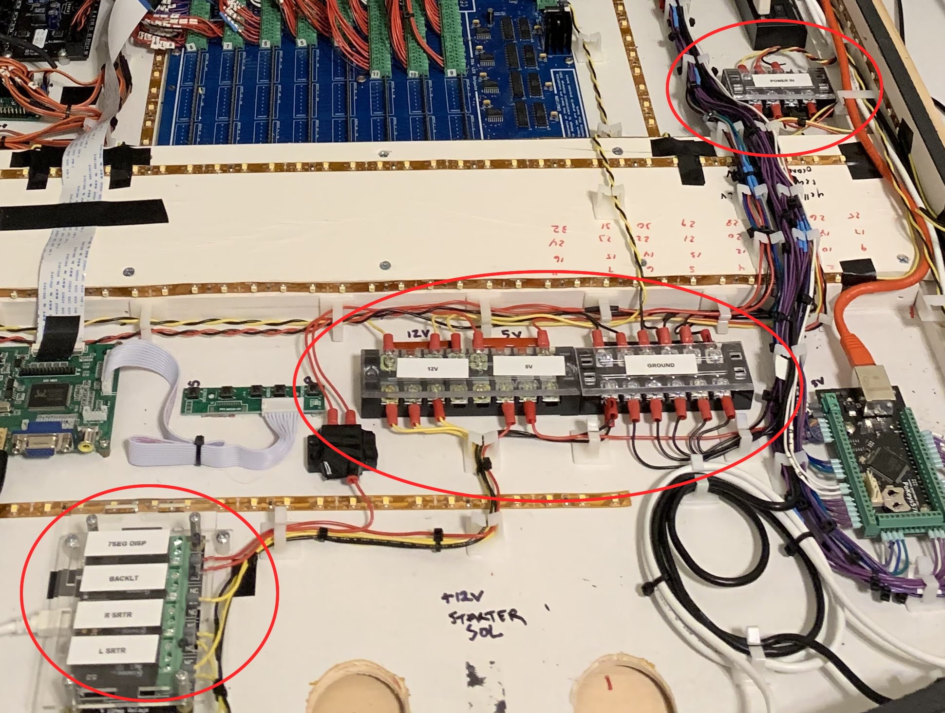
Power Distribution
How you are going to power the Overhead is something you need to think about early. Make sure you have a common ground, and ideally a single power supply. A fanless indisutrial power supply is perfect because you can find them with both 12V and 5V for inexpensive.
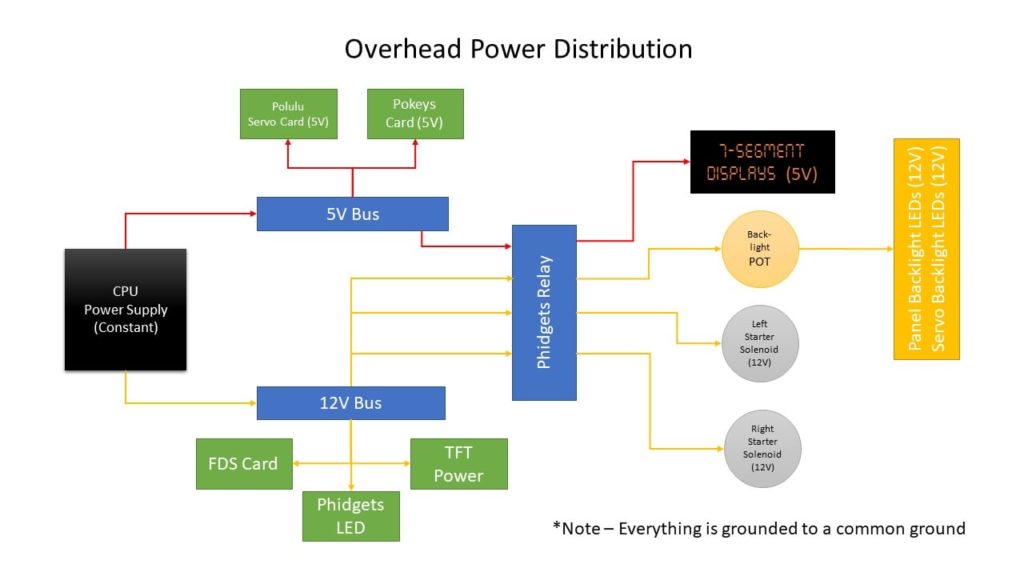
I finally settled on he following power configuration. This configuration allows me to power and control various overhead systems with relays. It works quite effectively.
I used a several power distribution bars inside the overhead: one for 12V, another for 5V, and another for Ground. This gave me a central place within the overhead to connect always-on power to.
The following diagram shows my final power distribution setup. Note that there is a relay which activates certain circuits based on Prosim events.
The starter switches are magnetically held, for example. They should only activate when Prosim tells them to during the starter sequence. The Phidgets relay allows Prosim to do that. Backlighting and 7-segment displays should only come on when aircraft AC power is activated within Prosim.
Power Issues
Here’s something to pay close attention to.
I found the 22-gauge wire used to run power to the overhead was not sufficient. The thinner wire combined with the long wire run from the power source to the overhead was causing “brown outs” under heavy load. This was especially noticeable when back-lighting was set to full bright and the starter solenoids were engaged.
The resultant power loss killed power to the interface cards and caused flickering of the indictor lights.
To ensure steady power under heavy loads, use sufficiently heavy gauge wire. I would suggest no less than 16 gauge. Once I replaced the 22 gauge power feed wire with 16 gauge the issue went away.
However, for all the wiring internal to the Overhead, 22-24 gauge wire was enough.
Panel Lights
CockpitSimParts panels are made of white acrylic plastic and painted gray. The lettering is laser etched into the paint. This allows the panels to be lit from the back and the light shines through the etched areas.
The concept sounds easy. However, trying to scatter light evenly within the confines of the overhead when you have wires and interface boards blocking the light’s path is not easy. This can cause a mix of inconsistent panel lighting.
The real aircraft, on the other hand, uses small aircraft bulbs inserted into the panels themselves. The light scatters more effectively and consistently. FlightDeck Solutions makes their panels this way and so their panel lighting is much more consistent. It also means you don’t have to be as careful with your wiring and board placement.
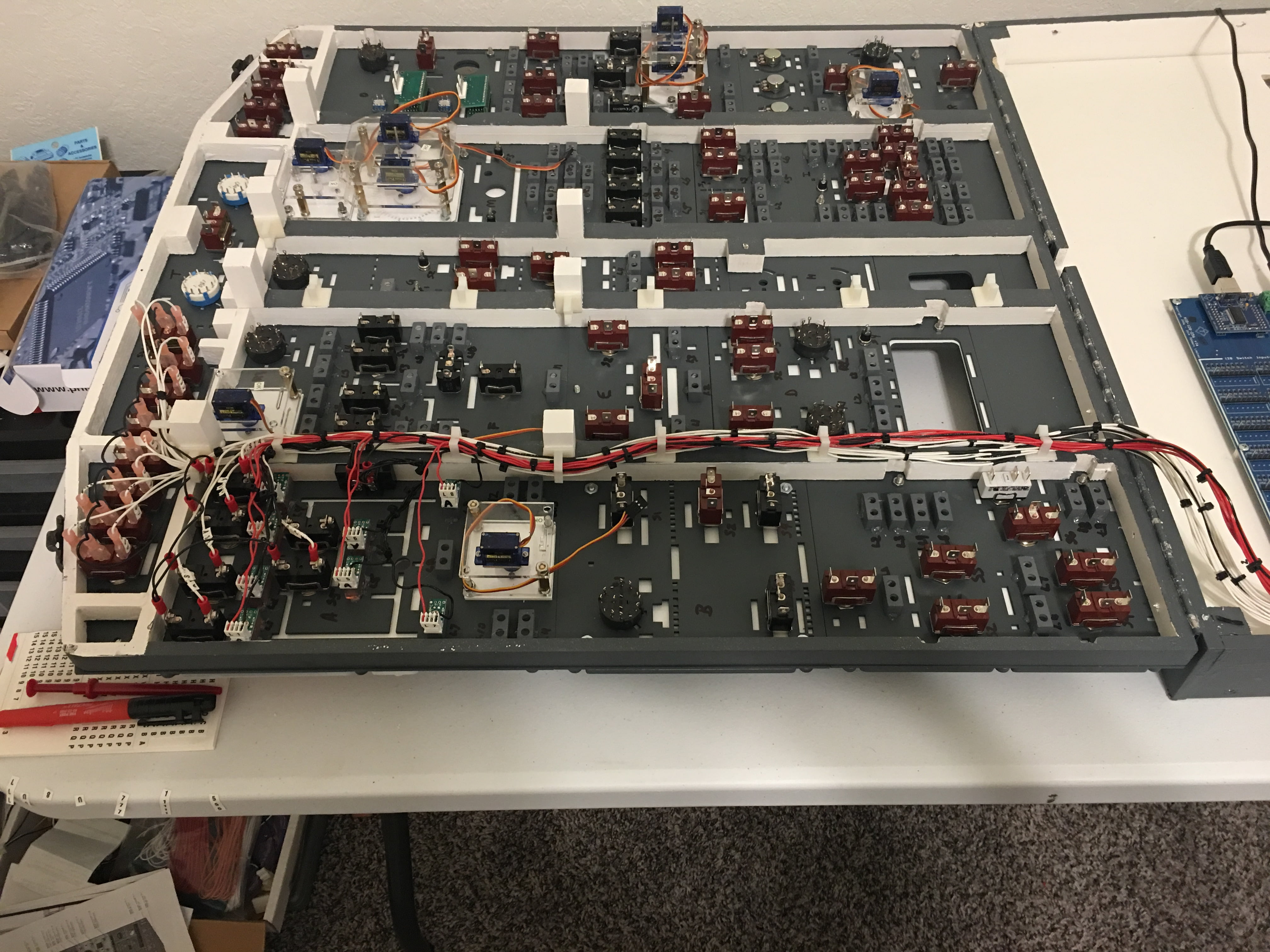
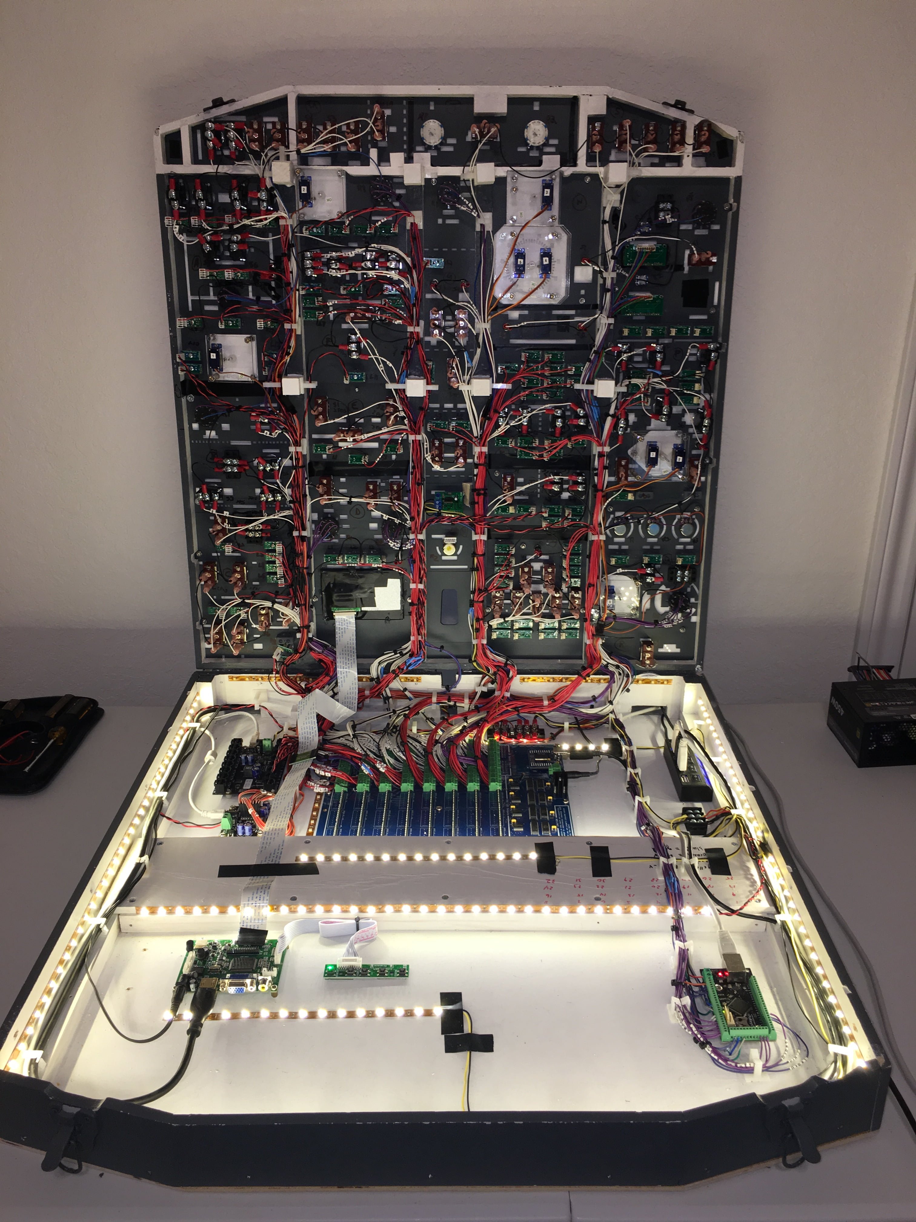
I did the best I could by putting as many 12V warm white LED strips throughout the interior of the overhead box, hoping to create enough light toreduce the inconsistent lighting. That is also why I painted the interior white to help reflect light internally. And that is also why my wiring is channeled into bundles as much as possible to reduce the blockage of light to the back sides of the panels.
While my method worked, it was not as good as I hoped with some areas still brighter than others.
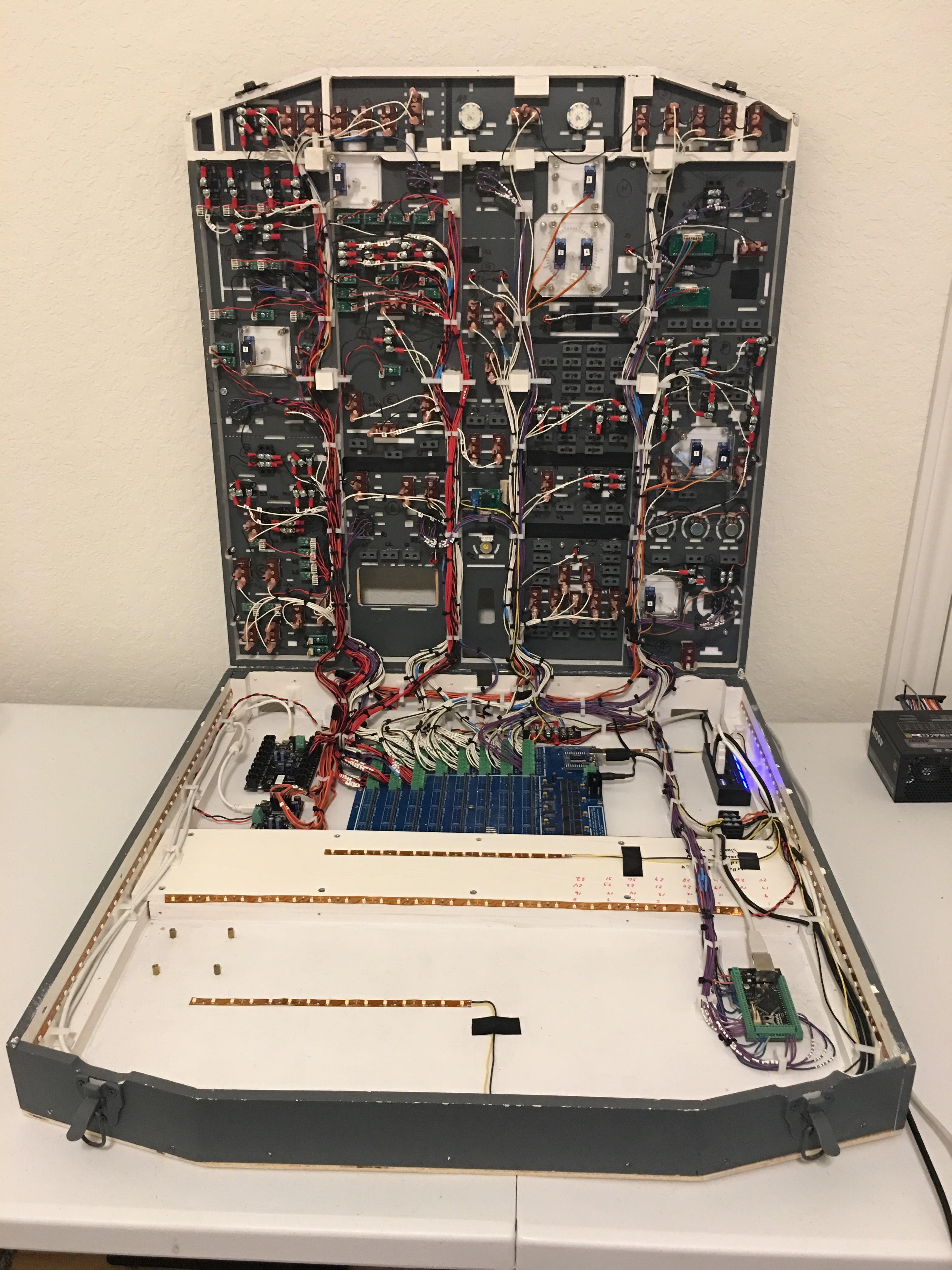
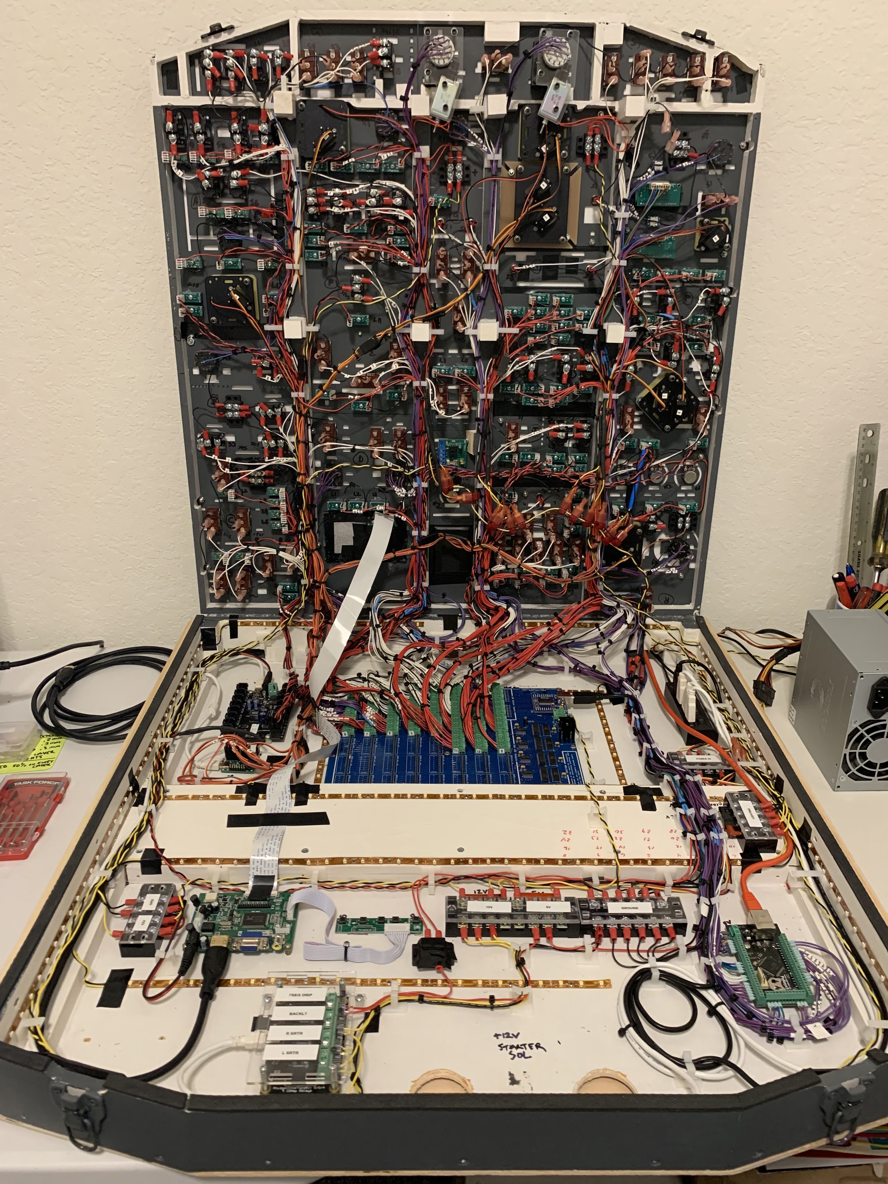
As you can see by looking at my Overhead interior, it’s not always easy to put lighting exactly where you want it. For example, the large FDS SYS4X interface board takes up a huge area that I cannot light with LED strips. So that area is much darker than, say, the front of the Overhead where there are less obstructions.
So, when planning out your overhead build make sure you take think about back lighting from the start.
The End Result
Once everything is finally wired up and working pat yourself on the back. This isn’t easy and you’ve accomplished something pretty amazing!
Just to give you an idea of what mine looks like in its completed state, here you go:

Some Things to Avoid/Think About
It is hard to plan for every situation and know what you’re going to need. Especially if you’ve never wired an overhead before. But try to do as much planning as you can in advance.
Some things to think about:
What kind of FRAME are you going to use?
You can also opt to buy pre-made metal frames from many of the popular sim vendors. FlightDeck Solutions, for example, makes frames that are DZUS compliant. They use the real-world mounting rails so you can move panels around or use real panels in combination with theirs. Other frames have fixed position holes, meaning you’re stuck with their layout and likely have to buy their panels to guarantee a fit. If you go with a pre-made frame, it’s best to stick with that vendors panels to guarantee a perfect fit.
What materials to use?
Is the frame going to be open or enclosed?
How are you going to access internal components?
The real aircraft has a swing-down overhead, allowing you to get behind the panel pretty easily. I added piano hinges and latches so I could easily swing down the panels to get behind them without taking the whole thing down.
If you have an open-style overhead frame, you still need to get behind it to perform maintenance. FlightDeck Solutions’ overhead frames, for example, swing down like the real aircraft for maintenance. But it is an open design so you need to find a place to mount the interface boards.
What kind of panels are you going to use?
There are many individual panels on the 737 overhead. Many sim vendors sell them, either as partial or complete kits, or plug and play. Some plug and play panels require proprietary boards to plug into. Some use wire harnesses, others use ribbon cables. Keep in mind that wiring can get very complex so the easiest solution is best.
Switches, Rotaries and Potentiometers
The 737 overhead has a variety of switches and potentiometers (see my diagram below). Most are two or three position. Some have one of the positions being momentary (spring loaded back to center). There are also locking switches that require you to pull out the switch stalk to move it to a different position. It all depends on how real you want to get.
You have several types of potentiometers. Some are just freely rotational like the AC temperature dials. Others are multi position potentiometers having 3 or more selectable positions.
Keep in mind the more you add the heavier the overhead will get.
Overhead Switch Diagram
I created the following diagram to help identify what types of toggle switches you’ll need to populate the Boeing 737NG overhead. I may do a separate drawing at some point to show the types of potentiometers and rotary switches you’ll need.

Overhead v1 Photo Gallery


8 comments
Skip to comment form
Hi,
I’m building a similar overhead using the FDS SYS 4X….and I just wired up my first set of LED’s. Disappointment is that they are very DIM. When I test them direct and thru my wiring with an alternate 3V source, they are quite BRIGHT. When I test the output of the FDS outputs, I get 3.05v. I repeated this with solitary LED’s, just to disqualify a short in my actual wiring. I also tested this directly at the board…to eliminate the potential for a long cable run dropping potential.
So…I should be seeing quite bright LED’s with the FDS SYS4X …but I am not. Any thoughts? Were your LED’s bright on your overhead? (Yes…I know you have moved on to the next level…but thought I’d ask!)
Thomas
Author
Hi Thomas, I haven’t had any issues with my SYS4X and the LEDs not being bright enough. I have had issues with some LED outputs not working correctly (like they shorted out or something).
I assume you’re using Prosim? I think there’s an LED brightness slider, but I don’t recall if it affects FDS LED brightness. Worth a shot.
Also, what PCB’s are you using with the LEDs? I assume there isn’t a resistor on them which could lower the output voltage right? I know my FDS PCBs don’t have resistors unless they are two stage brightness PCBs, and there’s only a handful in the overhead. But the fact they are bright when not using the board leads me to believe that isn’t the issue.
And you didn’t shave your LEDs flat, right? I remember seeing people say shave your LEDs down so they are flat tipped instead of round, which supposedly improves the light spread. I found that actually dims them. Again, since brightness is not an issue when not using the board this probably isn’t it either.
So I’d try giving the brightness slider a shot and see if that makes a difference.
MB.
Thanks for the very quick response! I am just running the basic hardware right now in test…no software involved other than the FDS control SW.
I did some further measurements this evening and saw that the voltage off the FDS board is coming off at 1.8v. My LED’s seem to be at 2.2-2.5v, so that could be an obvious dimmer factor. I had assumed FDS output at 2.5-3v. No resistors at play, other than what FDS has on the board.
I’ll try ordering some lower voltage LED’s and see how that goes.
Again, thanks a ton…and your site has been a HUGE help in planning my own sim. Will drop you some fotos when it’s up and going.
Thomas
Hi
i am busy building my overhead panel for the 737 but am struggling and i feel out of my depth as i am not the best at electrical work i have all the switches knobs gauges all fitted and have the relevant interface boards, but i feel I’m a long way off and need guidance its great to look at different guys work but im way short of that anyway yours looks fantastic, i was wondering what thickness off wire you use to wire the switches etc, also if i was to get really bogged down i wonder if you know of anyone or any firm who would finish off a partly started 737 forward overhead panel to plug and play. I have been flt simming for a number of years and have quite a lot of stuff from goflight, saitek etc I hope i haven’t wasted your time with my bumbling.
Regards
William
Author
Hi William, thanks for your question and kind words. I don’t know anyone who can take over the build, but I’d say just keep at it and you’ll get there. Sounds like you’re off to a good start. The overhead is the single most complicated wiring project in the entire sim and it takes some planning, some trial and error, and a lot of time. My first overhead took me 2-3 months to build. Even my second time around when I knew what I was doing it still took around a month and I still had times I felt a bit overwhelmed, so don’t feel like you’re alone.
I believe I used 22 gauge wire for all the switches and LEDs but it may have been 24 gauge. Either way, 22-24 gauge is ideal for the LEDs and switches since those carry very low voltages. If you know something will carry more voltage (like 12-28V) and higher amps (over 2A, I’d say) then you may want to bump up to thicker wire. I typically run 16 gauge from my power supply to any central power distribution points, especially if you’re carrying voltage over long distances so you minimize voltage drop. I’m no expert though, so as always do your research.
Hope that helps a little!
Tony
Hi,
Is it possible you send a few of those key caps to me?
Thanks.
Hi,
Great work! I’m trying to build the overhead myself too. I have a question: how did you create the light gray face panels with the lines in dark gray (the fuel, electrical and A/C panels)? Did you use white acrylic sheets which are painted dark gray first and then light gray and after that laser engrave at different depths to reveal the different color?
Thanks!
Author
Thanks. I didn’t make the panels from scratch. I purchased them from CockpitSimParts in the UK. Very reasonably priced and very accurate with sizing and markings. They were, however, about 1mm thinner than the OEM (at least many years ago when I bought them originally). The problem is they are back-lit which makes lighting them more challenging versus integrated back lighting like the FlightDeck Solutions IBL panels in my v2 Overheads.
That said, there are great videos on YouTube by Karl Clarke and Michael Schulz where they walk through creating panels from scratch. I recommend watching those to get some ideas. I haven’t made any myself yet (though I plan on it at some point). Hope that helps!