
Last Updated on September 27, 2019
Lately I have been in the process of disassembling the entire sim to paint the floor and shell, so while I had everything apart I decided to do some updates on my home-built overhead.
Goals
Goal #1 was to reduce the number of wires coming out the back of my overhead. Between the power adapters, HDMI cable, ethernet cable, and CPU power supply input, it was just too unmanageable.
Goal #2 was to re-wire the power in such a way as to allow me to control, via USB relays, when the power was turned on and off per the aircraft DC and AC power buses.
Re-wiring Power to Reduce Wires and Control Power Distribution
I have the following items in the overhead that require power:
- FlightDeck Solutions FDS Board to control most switches and LEDs (12V)
- Phidgets LED card to control dual-brightness LEDs (12V)
- PoKeys Ethernet board to handle remaining switches FDS board couldn’t (5V)
- Phidgets Relay Card (no power required; determined by input at each relay)
- Polulu Mini Maestro 12-servo Controller Card (5V)
- FlightSimParts.eu 7-Segment displays for ALT/LDG (5V)
- TFT controller board (12V)
- Full complement of CustomSimParts servo gauges (5V)
That’s a lot of stuff to power, and many of those items had bulky power adapters that came with them. I needed to consolidate as much as I could to simplify my overhead installation later. I already had 12V and 5V power coming in from a modified CPU power supply which was good since everything in the overhead is powered by either 12V or 5V.
The tricky thing is that some OH systems are powered when AC power buses are active. For example, the 7 segment displays and back-lighting only come on with AC power. The starter solenoids obviously only come on during engine start to hold the knob in the start position and then they release. So this required some things to be controlled by a relay card. Using a relay I can turn on/off those relay-connected items via ProSim using gates.
Below is a diagram of how I wired up my OH power. All the items that need constant power can get it from the moment the CPU power supply is turned on, and the relay-connected items would only receive the correct power when switched on by the software.
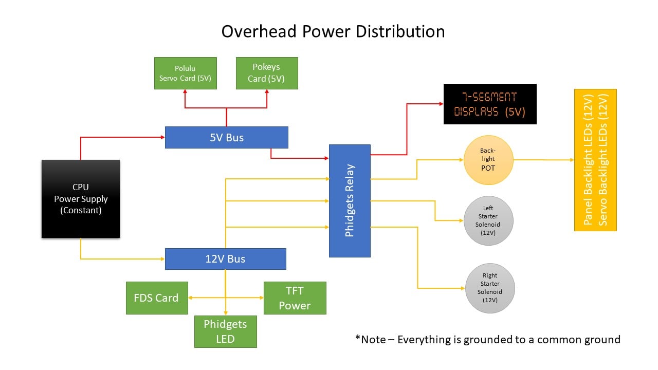
In the above diagram you can see the constant 12V and 5V power comes in from the CPU power supply and goes to terminal distribution blocks. I purchased terminal blocks on Amazon that had plastic covers to reduce the chance there could be short circuit. I also made sure all ends were terminated properly with fork connectors so none of the power wires can easily come free.
From the distribution blocks constant power is distributed to the various cards that need it, or it is passed to the relay card which, when activated, feeds the input power to the respective connected devices.
The 7-Segment displays only come on when AC power is turned on. The relay allows that to happen.
The same with the panel back-lighting. It only comes on when AC power is on. You’ll note in the diagram above that I added the dimmer POT for the panel and gauge back-lighting brightness after the relay. This allows me to feed a constant 12V to the relay and control the on/off of the back-lighting, but then when the relay is turned on I can then also control the variable panel brightness from zero up to full bright. If I put the POT before the relay, when the dimmer is set to zero no power will flow to the relay and I believe the relay needs at least a minimum amount of power to activate.
On a related note…the CustomSimParts gauges I use have back-lighting that will work with both 5V or 12V. The gauges have a built-in resistor to keep the 5V LEDs from burning out. However, I was told by CustomSimParts that although the gauges will work fine with 12V, if you choose to go that route it’s better to add an in-line 150-200 Ohm resistor in front of them to reduce wear. Since I’m using 12V for the backlighting I soldered in a 200 Ohm resistor in-line to each gauge which turned out to work perfectly. The brightness doesn’t overpower the case back-lighting.
All said, doing this allowed me to get rid of 4 power adapters (FDS card, Phidgets LED, TFT power, Pokeys card). I am still left with one power adapter for the 4-port USB hub. For some reason it would not accept power from my buses, so I am stuck using its adapter for now and it is necessary to ensure the USB-connected devices have enough USB power to run.
Below is a picture of how the wiring turned out. The power is not placed as nicely as I would have liked, primarily because I lost space due to the hump in the middle of my overhead cabinet, limiting where I could put components.
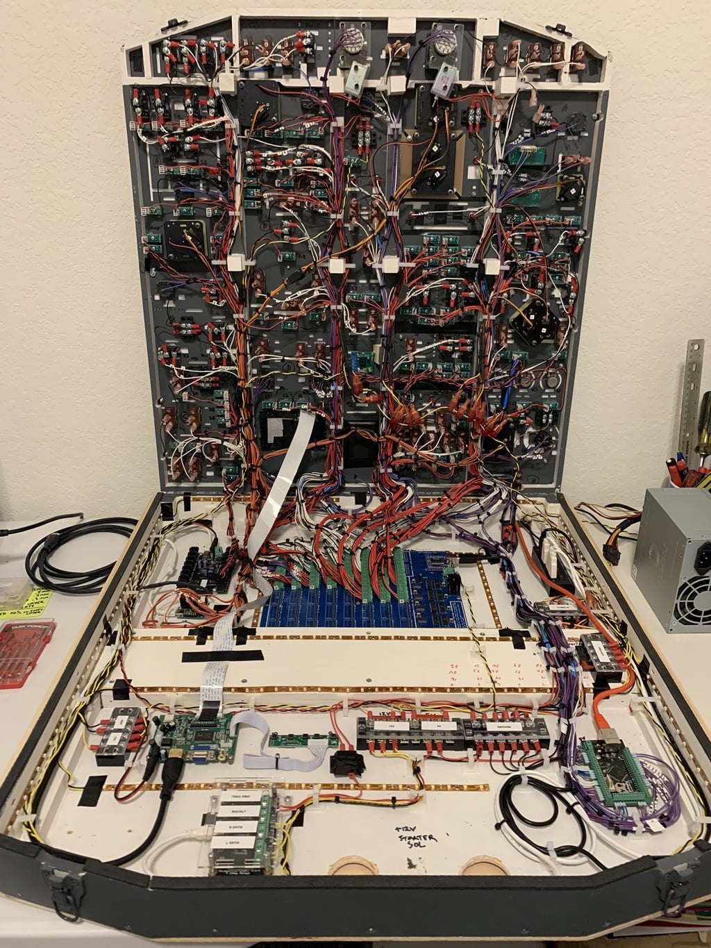
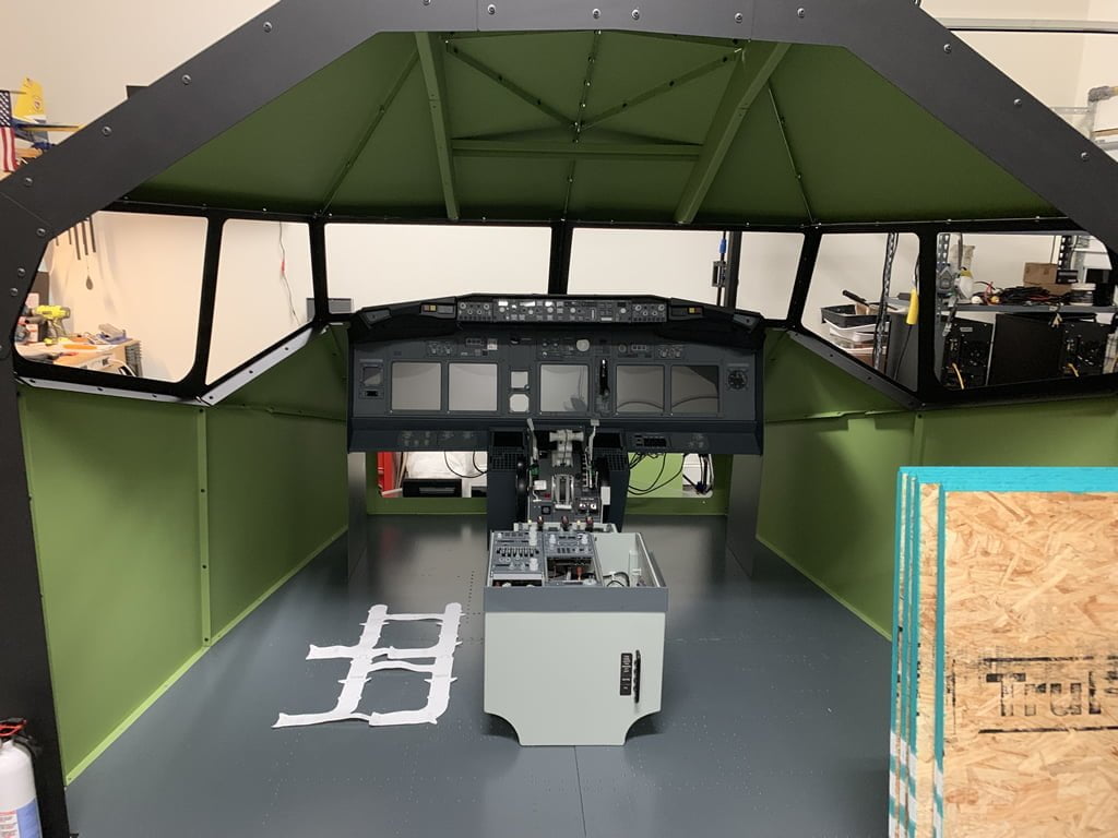
The hump in the middle was necessary to clear the FDS cockpit shell crossbeam. If you plan on never using the FDS drop-down overhead frame in your FDS shell then you can remove the crossbeam and thus not need the hump freeing up valuable space. However, in the future I may switch to FDS panels, so I left the cross beam in place. You can see the OH crossbeam in the image below.
Conclusion
I hope this article gave you some ideas on how to wire power for your overhead.
One thing to mention…I haven’t added in any fuse blocks which really should be done to prevent any shorts from burning up the overhead components or starting a fire. While the FDS card has a built in fuse the other cards and components don’t. Fortunately the CPU power supply has short protection so it will cut out if a short is detected. And I’ve been very careful to make sure all my connections are solid and protected. I have been lucky so far, but you never know. Better safe than sorry. If you are planning a build, I recommend you consider putting in fuse blocks as well.


6 comments
Skip to comment form
My new overhead project is coming along really well, your detailed explanation has made life much easier. Could you please tell me which Phidgets relay card you used?
Thank you,
Philip
Author
Hey Philip, glad I could help a little. I have so many more updates to put out there. Just haven’t had enough time to get them posted.
Regarding the Phidgets relay, I used the PhidgetInterfaceKit 0/0/4. It can be found at: https://www.phidgets.com/?tier=3&catid=46&pcid=39&prodid=1020
It is a breeze to use and works flawlessly, plus integration with Prosim is seamless. Definitely worth it!
Best,
Tony
What gauges did you use? Did you use the Cockpitsimparts gauges or CustomSimparts? If you used the CustomSimParts, were the mounting holes the same to fit the Cockpitsimparts OVH Panels. I have the same panels, using the CockpitSimparts gauges. Im debating on the Customsimpart gauges as they are already backlit.
Your OVH frame looks fantastic. Wiring too. Alot better than mine….. Time to redo, to clean things up.
Regards,
Eric
Author
Hi Eric, I originally used the CockpitSimParts gauges, but switched to the CustomSimParts ones later. Most of the mounting holes were the same but there were some, and I can’t remember which, that I had to modify the holes on the gauges to make them fit. The CustomSimParts gauges are quite nice, especially at the price point. The only downside is the markings are not very visible when the backlighting is off. I can live with that as the quality otherwise is worth the price.
Appreciate the overhead comments. That was probably a couple months of work and there are things I definitely would do different, but it’s 99% functional with the exception of the two magnetic toggle switches. I’m working on a version 2 now, which is a complete FDS overhead frame and panels. Once that’s finished I’ll swap them out and probably part the old one out.
Nice work.
I am doing mine with FDS SYS1/FDS Relay card and Input card. also using Pokeys for 7Segment displays. I add some photos later on. I am bit confuse with how to get Starter Solenoids to work with relay card. I know how to connect them but doesn’t turn off automatically when reach limit. anyone has idea how to do them? that would be Appreciate.
thanks
kind regards Kapila
from Australia.
Author
Hi, I’m not sure how FDS relays work, but I venture it’s the same or similar to the way Phidgets works.
First, I have the starter switch positions set up for Off, GRD, CONT, and FLT in Prosim config under Pneumatic > Switch > Start 1 Off, Start 1 GRD, etc. Make sure each starter’s switch positions work correctly.
Then, in Prosim config I have configured the respective relay outputs for each starter switch under Pneumatic > Gate > “Starter 1 soelnoid” and “Starter 2 solenoid”.
If your relay is configured correctly then when the starter 1 switch is turned and held in GRD, it activates the gate for starter 1 solenoid which in turn activates the relay for starter 1 solenoid and the starter 1 magnetic switch holds the position. Once N1 is at the right RPM, Prosim automatically turns off the gate which cuts power to that relay output and allows the magnetically held switch to return to spring-loaded Off.
Hope that helps.